Operational Specifications
3.2.2 Switch and LED Functions
Rev.1.00 June 1,2005 3-15
REJ11J0002-0100Z
3
3.2.2 Switch and LED Functions
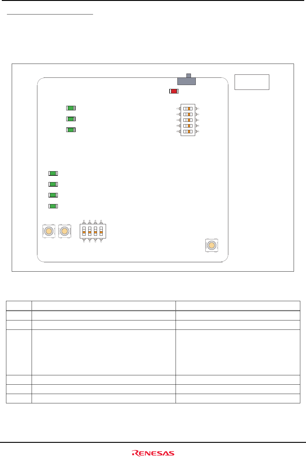
The M3A-HS60 includes six switches and eight LEDs.
Figure3.2.3 shows the M3A-HS60 Switch and LED Pin Assignment.
Table3.2.3 lists the switches mounted on M3A-HS60.
LED1
SW4
O N
54321
SW2 SW5
RST
SW1
ON OFF
SW3
1234
O N
4321
NMI
Top view of the
component side
PA18
PA19
PA24
PA25
LED2
PE1
LED5
LED4
LED3
PE2
PE8
PE10
LED6
PE11
LED8
LED7
PE14
PE15
SW6
MRES
Figure3.2.3 M3A-HS60 Switch and LED Pin Assignment
Table3.2.3 Switches Mounted on M3A-HS60
No. Function Remarks
SW1 System power on/off switch -
SW2 System reset input switch Refer to section 2.8 for details
SW3 User DIP switch (4-pole)
SW3-1 OFF:PA18=H,ON:PA18=L
SW3-2 OFF:PA19=H,ON:PA19=L
SW3-3 OFF:PA24=H,ON:PA24=L
SW3-4 OFF:PA25=H,ON:PA25=L
PA18, PA19, PA24, and PA25 are pull-upped.
Refer to section 2.5 for details
SW4
System setup DIP switch (5-pole) Refer to Table 3.2.4 for function lists
SW5
NMI interrupt switch
Refer to section 2.9 for details
SW6
Manual reset switch
*1
Refer to section 2.9 for details
*1
Although an internal state of CPU is initialized in manual reset, each register of the on-chip peripheral module is
not initialized
.


