


(3/4)
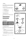
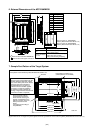
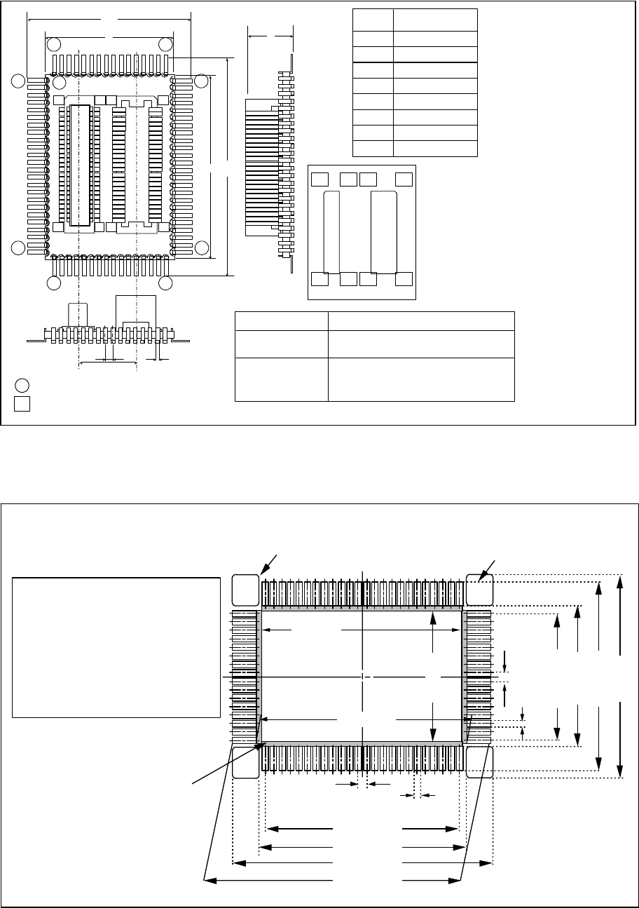
6. External Dimensions of the M3T-DUMMY80
Figure 3 External dimensions of the M3T-DUMMY80
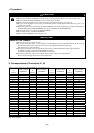
7. Sample Foot Pattern of the Target System
Figure 4 Dimensions of a target foot pattern (Quoted from the specifications of IC socket for QFP by Matsushita Electric Works, Ltd.)
M
J
1
J
2
Upper connector J1: AXN650585P
(made by Matsushita Electric Works, Ltd.)
Upper connector J2:
AXN550045P
(made by Matsushita Electric Works, Ltd.)
: Pin number of the upper connectors
: Pin number of the M3T-DUMMY80
b
e
D
HD
E
HE
A
Material: Glass epoxy boardBoard
Upper connectors
(J1, J2)
Material: Heat tolerant resin (body)
Copper alloy (post, contact)
Plating: Nickel-based gold plating
Material: Bronze phosphide
Plating: Solder plating
Pin
1
1
1
24
25
40
41
64
65
80
1
25
26
25
26
50
1
50
1
50
1
50
25
26
25
26
A
Symbol
b
D
E
e
M
HD
HE
0.3
0.8
24.0
18.0
20.0
14.0
5.0
6.3
Dimension: [mm]
Foot pattern recommended by Matsushita Electric Works, Ltd.
Foot pattern for holders (x 4)
(These patterns are essential.)
0.80±0.05
0.80±0.05
0.50±0.05
0.50±0.05
max. 19.0
max. 13.0
4-R 0.25
Note:
Be sure to set up foot patterns for the
holders. Make the thickness and the
area of the solder-print screen thicker
and larger than the foot patterns
recommended so as to secure a
sufficient amount of solder applied.
(In carrying out manual soldering,
an amount of solder sufficient for
forming a larger fillet than that formed
at the time of reflow is required.)
As the contacts of the IC
socket body touch the PC
board, thus be sure to give
special consideration to the
patterns of traces so that no
other pins touch the PC
board.
(Through-hole mounting is
not permitted.)
21.00±0.1
18.40±0.05
19.50±0.1
min. 26.50
26.50±0.1
12.00±0.05
15.00±0.1
20.50±0.1
min. 24.0
Unit: mm