


4. Usage (Emulator Debugger)
The required operating environment is described below.
- Integrated development environment: High-performance Embedded Workshop
- Emulator debugger: M32C Compact emulator debugger Ver.1.00 Release 00 or later
(The emulator debugger “M3T-PD308MF” can not be used.)
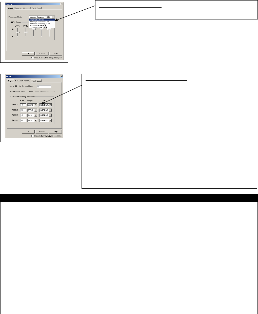
Set the emulation memory in the Emem dialog box of the emulator debugger start-up.
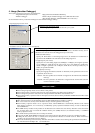
1. Specifying the processor mode
Specifying the processor mode
Select the appropriate processor mode that suits your system.
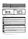
2. Emulation memory allocation for an extended area
Emulation memory allocation for an extended area
When memory expansion or microprocessor mode is selected, emulation memory can be
allocated to the extended area to be debugged (in up to four areas).
* Bank (Set bank address)
Specify the bank address of the debug target area to be allocated in hexadecimal. If
specified as d0, D00000h is the start address of the debug target area.
* Length (Specify size of area)
Specify the size of the debug target area (256Kbytes or 1Mbytes). If Length is specified
to be “256Kbytes”, banks 00, 04, 08, and up to FC (every four banks) are specified for
Bank; if Length is specified to be “1 Mbytes”, banks 00, 10, 20 and up to F0 (every 16
banks) are specified for Bank.
* Map (Specify area map)
Specify the mapping information (“Internal” or “External”) in the specified area. If no area
is specified, select “No Use”
- Internal : The area specified to be “Internal” is mapped into the internal area (emulation
memory).
- External : The area specified to be “External” is mapped into the external area (external
resource in the user system)
IMPORTANT
Notes on Selecting a Processor Mode of the M30850T3-CPE:
z When setting single-chip mode, do not connect to this product.
z When setting memory expansion mode, the level of the pin CNVSS of the MCU status should be "L".
z When setting microprocessor mode, the level of the pin CNVSS of the MCU status should be "H".
z When setting memory expansion mode or microprocessor mode, the level of the pins RDY# and HOLD# of the MCU status
should be "H".
Notes on Using Expansion Emulation Memory:
z MCU internal resources are automatically selected as SFR and RAM areas regardless of settings.
z For a reset vector area, memory of the emulator is always selected regardless of the setting
z When memory expansion mode is set as a processor mode, internal ROM area is automatically allocated to the internal
Flash memory. Therefore, it is not necessary to deliberately specify expansion emulation memory in order to allocate the
internal ROM area.
z The 4MB memory mounted in the product can be allocated to the external area. Set memory allocation so that the total of
the 4 Length values does not exceed the emulation memory size (4MB). However, the emulation memory is 3.25MB in
memory expansion mode.
z Be careful that the specified areas do not overlap one another.
z Except for the SFR, RAM, ROM and internally reserved areas, all areas other than the set area are externally accessible.
z In Map, the areas where “No Use” is selected, and is unspecified are allocated to external resources. When “External” is
specified, only the downloaded speed is different.
z Do not set the following areas for memory allocation of the MCU. Set these areas referring the specifications of the MCU.
(1) Area allocated for multiplex bus (2) Unusable area
(3/4)