


8
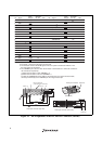
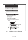
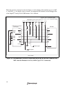
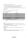
When the circuit is connected as shown in figure 1.3, the switches of the emulator are set as SW2
= 1 and SW3 = 1. For details, refer to section 3.8, Setting the DIP Switches, in the Debugger Part
of the SuperH
TM
Family E10A-USB Emulator User’s Manual.
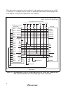
H-UDI port connector
(36-pin type)
SH7339
Reset signal
1
AUDATA0
AUDATA2
AUDATA1
AUDATA3
TCK
TMS
AUDSYNC
N.C.
CA
RESET
TDI
TDO
TRST
ASEBRKAK
UVCC
GND
GND
GND
GND
(GND)
GND
GND
GND
GND
GND
GND
GND
GND
GND
GND
GND
GND
GND
GND
3
5
7
9
11
13
15
17
19
21
23
25
27
29
31
33
35
2
4
6
8
12
10
14
16
18
20
22
24
26
28
30
32
34
36
AUDATA0
AUDATA2
AUDATA1
AUDATA3
TCK
RESETP
TMS
TDO
TDI
TRST
ASEBRKAK
AUDCK
AUDSYNC
AUDCK
N.C.
VccQH
All pulled-up at 4.7 kΩ or more
ASEMD0
1 kΩ
VccQ
User system
CA
/CA signal
VccQ
VccQH = 3.0-V I/O power supply
VccQH
VccQ = 3.0-V/1.8-V I/O power supply
VccQHVccQH VccQH
VccQH
Figure 1.3 Recommended Circuit for Connection between the H-UDI Port Connector and
MPU when the Emulator is in Use (36-Pin Type UVCC Connected)