


10
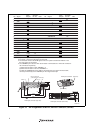
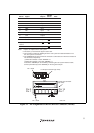
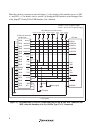
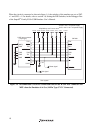
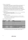
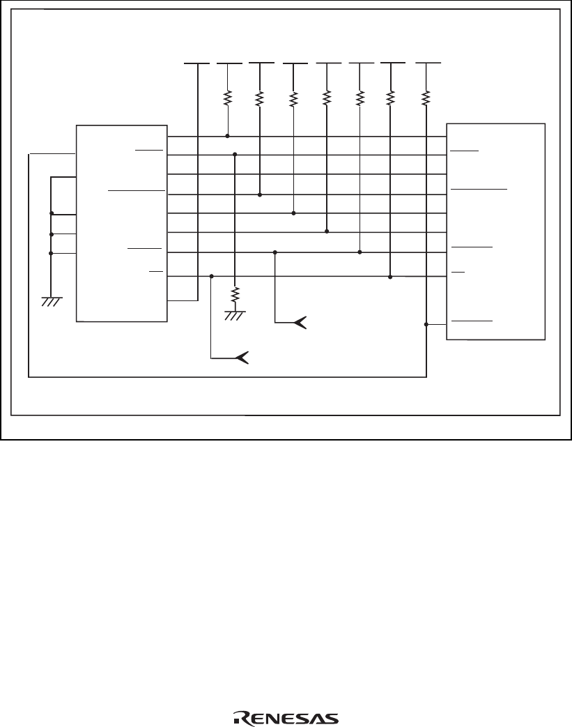
When the circuit is connected as shown in figure 1.4, the switches of the emulator are set as SW2
= 1 and SW3 = 1. For details, refer to section 3.8, Setting the DIP Switches, in the Debugger Part
of the SuperH
TM
Family E10A-USB Emulator User’s Manual.
1
TCK
TMS
RESET
TDI
TDO
TRST
ASEBRKAK
GND
GND
GND
GND
(GND)
2
3
4
5
6
7
ASEMD0
8
9
11
10
12
13
14
TCK
RESETP
TMS
TDO
TDI
TRST
ASEBRKAK
CA
UVCC
CA
H-UDI port connector
(14-pin type)
SH7339
Reset signal
1 kΩ
User system
/CA signal
VccQ
All pulled-up at 4.7 kΩ or more
VccQH = 3.0-V I/O power supply
VccQ = 3.0-V/1.8-V I/O power supply
VccQH
VccQ
VccQHVccQH
VccQH
VccQH
VccQH
Figure 1.4 Recommended Circuit for Connection between the H-UDI Port Connector and
MPU when the Emulator is in Use (14-Pin Type UVCC Connected)