


15
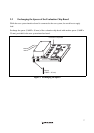
Section 3 User System Interface Circuits
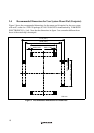
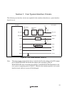
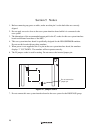
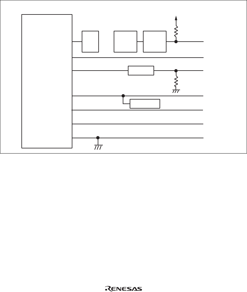
The following user interface circuits are required for the emulator when the user system interface
board is in use.
Sub-MCU
MD control
circuit
Monitoring
circuit
LPT16244
MD_CLK
Vcc
47 kΩ
PM0-PM4
User system
VBUS
MD_CLK
DrVss
DrVss
PM0-PM4
VBUS
DrVcc DrVcc
USD-
USD-
USD+
USD+
Power-supply
circuit
EPM7128
1 kΩ
Figure 10 User System Interface Circuit (1)
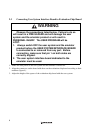
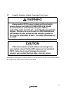
Note: The power-supply circuit shown above is turned on/off by the setting of the SW1 jumper
pin on HS1653ECN61H. Ensure that the jumper pin is inserted to [ON] on
HS1653ECN61H when connecting the emulator (with HS1653ECN61H attached) to the
user system or supplying power to DrVCC. Otherwise the emulator product, user system
interface board, and user system will be damaged.