


18
Section 4 Verifying Operation
1. Turn on the emulator according to the procedures described in the H8SX/1650 E6000H
Emulator User's Manual (HS1650EPH60HE).
2. Verify the user system interface cable connections by checking the pin states with the CHECK
command (emulator command) and checking the bus states with the FILL command (emulator
command). If an error is detected, recheck the soldered IC socket and the location of pin 1.
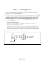
3. The emulator connected to this user system interface board supports three kinds of clock
sources as the MCU clock. For details, refer to the H8SX/1650 E6000H Emulator User's
Manual (HS1650EPH60HE).
To use the emulator internal clock
Select the clock in the emulator by the CLOCK command (emulator command).
To use the external clock on the user system
Supply the external clock from the user system to the emulator by inputting the EXTAL
pin (pin 84) on the user system interface board or connecting the crystal oscillator to the
XTAL (pin 83) and EXTAL pins. For details, refer to the H8SX/1650 Hardware Manual.
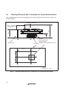
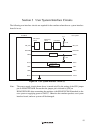
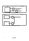
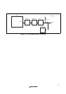
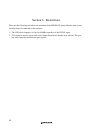
Figure 14 shows the clock oscillator on the user system interface board.
270 Ω
0 Ω
1 MΩ
HCU04
HCU04
HCU04
HCU04
EXTAL XTAL
HCU04
To E6000H
emulator
HCU04
System clock
Figure 14 Clock Oscillator