


6
RH5RH
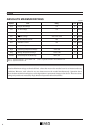
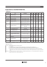
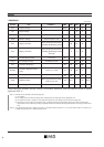
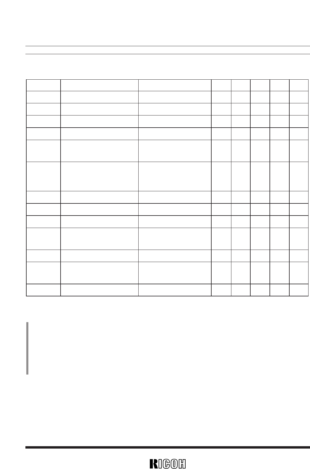
• RH5RH501A
VOUT=5.0V
Unless otherwise provided, VIN=3V, Vss=0V, IOUT=10mA, Topt=25˚C, and use External Circuit of Typical
Application (FIG. 1).
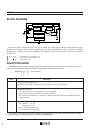
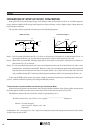
(Note 1) Soft-Start Circuit is operated in the following sequence :
(1) V
IN is applied.
(2) The voltage (Vref) of the reference voltage unit is maintained at 0V for about 200µs after the application of V
IN.
(3) The output of Error Amp. is raised to “H” level during the maintenance of the voltage (Vref) of the reference voltage unit.
(4) After the rise of Vref, the output of Internal Error Amp. is gradually decreased to an appropriate value by the function of Internal Phase
Compensation Circuit, and the Output Voltage is gradually increased in accordance with the gradual decrease of the output of Internal Error
Amp.
(Note 2) I
LX is gradually increased after Lx Switch is turned ON. In accordance with the increase of ILX, VLX is also increased. When VLX reaches VLXlim,
Lx Switch is turned OFF by an Lx Switch Protection Circuit.
Symbol Item
VOUT Output Voltage
VIN Input Voltage
Vstart Start-up Voltage
Vhold Hold-on Voltage
I
DD
1 Supply Current 1
IDD2 Supply Current 2
ILX Lx Switching Current
ILXleak Lx Leakage Current
fosc Oscillator Frequency
Maxdty
Oscillator Maximum Duty
Cycle
η
Efficiency
tstart Soft-Start Time
VLXlim VLX Voltage Limit
Conditions MIN. TYP. MAX. Unit Note
4.875 5.000 5.125 V
8 V
Iout=1mA,Vin:0→2V 0.8 0.9 V
Iout=1mA,Vin:2→0V 0.7 V
To be measured at OUT Pin
(excluding Switching Current)
30 45 µA
To be measured at OUT Pin
(excluding Switching Current) 2 5 µA
VIN=5.5V
VLX=0.4V 80 mA
VLX=6V,VIN=5.5V 0.5 µA
40 50 60 kHz
on (VLX “L” ) side 70 80 90 %
70 85 %
Time required for the rising
0.5
2.0
ms Note1
of VOUT up to 5V.
Lx Switch ON 0.65 0.8 1.0 V Note2