


2
RH5RH
×××× – ×× ← Part Number
↑ ↑ ↑
a b c
SELECTION GUIDE
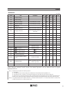
In RH5RH Series, the output voltage, the driver, and the taping type for the ICs can be selected at the user's
request. The selection can be made by designating the part number as shown below :
For example, the product with Output Voltage 5.0V, the External Driver (the Oscillator Frequency 100kHz)
and Taping Type T1, is designated by Part Number RH5RH502B-T1.
Code Description
Setting Output Voltage (VOUT):
a
Stepwise setting with a step of 0.1V in the range of 2.7V to 7.5V is possible.
Designation of Driver:
1A: Internal Lx Tr. Driver (Oscillator Frequency 50kHz)
b 2B: External Tr. Driver (Oscillator Frequency 100kHz)
3B: Internal Tr./External Tr. (selectively available) (Oscillator Frequency 100kHz, with chip
enable function)
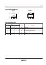
Designation of Taping Type :
c
Ex. SOT-89
:
T1, T2
SOT-89-5
:
T1, T2
(refer to Taping Specifications)
“T1” is prescribed as a standard.
RH5RH
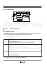
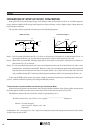
BLOCK DIAGRAM
Lx
Vss
EXT
LxSW
CE
Error Amp.
OUT
V
LX limiter
Buffer
PWM control
OSC
Chip Enable
Slow start
Phase Comp.
Vref
+
–
Error Amp. (Error Amplifier) has a DC gain of 80dB, and Phase Comp. (Phase Compensation Circuit)
provides the frequency characteristics including the 1st pole (fp=0.25Hz) and the zero point (fz=2.5kHz).
Furthermore, another zero point (fz=1.0kHz) is also obtained by the resistors and a capacitor connected to
the OUT pin.
(Note) Lx Pin
............
only for RH5RH××1A and RH5RH××3B
EXT Pin
.........
only for RH5RH
××2B and RH5RH××3B
CE Pin
...........
only for RH5RH
××3B
}
}
}