


INSTALLATION
6
CRYSTALVIEW DVI CATx INSTALLATION AND OPERATIONS MANUAL
Installation
Please refer to the safety section first before proceeding with any installation
or configuration of the CrystalView DVI CATX.
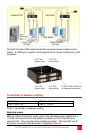
When installing the CrystalView DVI CATX, locate the transmitter as close as
possible to the CPU or switch. Keep the cables as short as possible but still
give some freedom of movement. Using shorter cables keeps the video noise
to a minimum and reduces installation costs. You can mount the CrystalView
DVI CATx in a CPU rack with the optional rack mount kit. When mounting the
units in a rack, follow the instructions in Appendix D and Appendix E. Provide
adequate air circulation to assure that the maximum operating temperature is
not exceeded.
Wherever the transmitter and receiver units are located, they should be on a
secure surface and free from obstructions and objects that may cause
damage to the units.
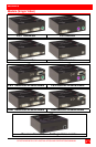
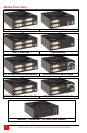
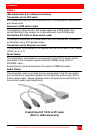
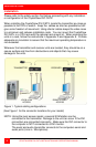
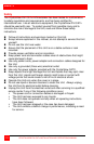
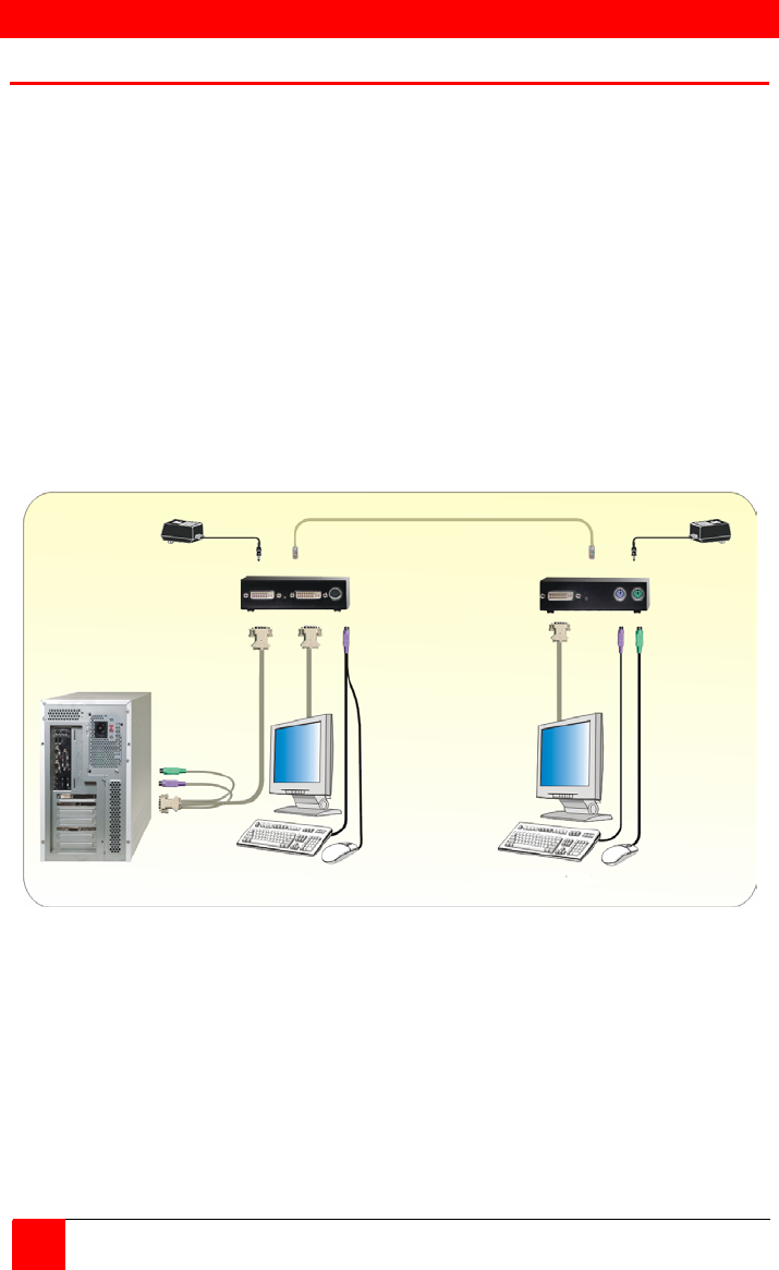
Figure 1. Typical cabling configurations
(See Figure 1 for the connector locations for your model)
NOTE: Using the local access model, a second KVM station can be
connected to the transmitter. Damage to the unit can occur if the DVI
connectors are connected incorrectly. Make sure the DVI connector to
the computer is NOT connected to a DVI monitor.
The serial and audio transmitter connects to the computers serial and
audio ports (Line in / Microphone).
LOCAL KVM REMOTE KVM
ACCESS ACCESS
TRANSMITTER RECEIVER