


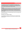

INSTALLATION
CrystalView Installation and Operations Manual
19
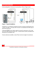
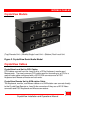
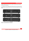
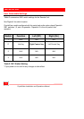
Step 2: Connecting the Cables
Power down your PC and connect the appropriate CPU cable to the Keyboard,
Video and Mouse ports on the CPU. Connect the other end of the CPU cable to
the Local Units Keyboard, Video and Mouse connectors. If the Local Unit is a
dual model, make sure you connect the cables to the connectors marked “TO
PC”.
(See the CrystalView Cables section and Appendix C. Parts and Cables)
Connect your KVM station’s Keyboard, Video monitor and Mouse cables to the
corresponding CrystalView Remote Unit’s Keyboard, Video and Mouse
connectors. If your Unit is a Dual version, you can also connect a second KVM
station to the Local Unit and access the CPU from either Unit independently but
not simultaneously. A lockout feature inhibits the “not-in-use” unit.
For the audio option, connect the “Line In” connector on the Local Unit to the
CPUs sound card “Line Out” connector using a standard 3.5mm stereo audio
cable. On the Remote Unit, connect a pair of computer speakers or a headset to
the “Line Out” connector.
(See
Figure 1
)
For the Serial option, connect the DB9F serial connector on the Local Unit to
the DB9M connector on the CPU using a standard DB9MF cable. Connect the
DB9M connector on the Remote Unit to your serial device.
(See Figure 1)
Finally, connect the CAT5 cable to the RJ45 jacks on both the Local and Remote
Units.
It is recommended that you test the complete system before permanently
installing the Local and Remote units.