


INSTALLATION
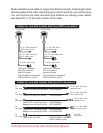
Step 1. Connecting monitor, keyboard, and mouse
1.1 Plug the monitor, keyboard, mouse, and speaker cables directly into
the rear panel of the unit.
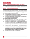
Step 2. Connecting the computers
CPU cables connect your computers to Vista Mini. Each computer requires its
own cables, with appropriate connectors for your particular CPU. CPU cables
are available from Rose Electronics. Refer to page 3 for using the proper cable.
For Vista Mini models with DB 25 connectors:
2.1 Plug the DB25 male connector of the CPU adapter cable into one of the
numbered CPU ports on the Vista Mini side panel.
2.2 Plug the CPU adapter cable’s monitor, keyboard, and mouse connec-
tors into the CPU’s corresponding ports.
For Vista Mini models with PC connectors:
2.1 Plug the HD15 male-male cable from the video card into one of the
numbered HD15 female connectors on the Vista Mini rear panel.
2.2 Plug the mini-din-6 male-male cable from the computer keyboard port
into one of one of the numbered mini-din-6 female connectors with a
keyboard symbol on the Vista Mini rear panel. If your computer has a
din-5 keyboard port use the mini-din-6 female to din-5 male adapter.
2.3 Plug the mini-din-6 male-male cable from the computer mouse port
into one of one of the numbered mini-din-6 female connectors with a
mouse symbol on the Vista Mini rear panel. If your computer has a se
-
rial port for the mouse use the mini-din-6 female to DB9 female adapter.
Warning do not substitute with a non-Rose adapter, there is a differ
-
ence, damage may occur if you use a third-party adapter!!!
2.4 Plug the 3.5mm stereo cable into the stereo jack.
6 VIStA MINI INSTALLATION AND OPERATION MANUAL