


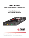

GETTING STARTED
To acquaint you with your Vista Mini unit, this manual first describes Vista Mini’s
front and rear panels. Then follow the installation on page 6, which is simply a
description of how to plug in the connectors.
Package contents
Your Vista Mini package includes the Vista Mini unit, your warranty registration
card, and this manual.
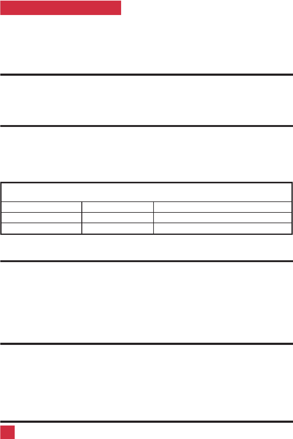
Vista Mini models
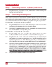
This manual describes two different models of Vista Mini, see Table 1 below.
The features and commands are the same, the only difference is the connector
type for the computers. Please disregard the diagrams and text that do not ap-
ply to your model. The models available are:
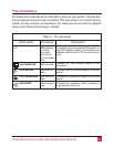
Table 1. Vista Mini models
Model Computers Computer connector
KVT-2U 2 PCs DB25 female
KVT-2PC 2 PCs PC (HD15F, MD6F, MD6F, 3.5mm)
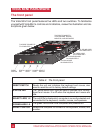
Locating the unit
The Vista Mini unit is best located as close to the CPUs as possible. This will re
-
duce the length of the CPU cables and provide a more cost-effective and neater
installation. While usage of the Vista Mini is trouble-free and transparent and
need not be in an accessible location, you may wish to access the front panel to
observe the LEDs, switch to a computer, or reset the unit.
Cable requirements
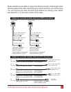
Vista Mini connects to each computer with various cables, depending on which
model and computer type, see the next page for the different cable types. You
plug the keyboard, monitor, mouse, and speakers directly into Vista Mini. The
cables are most commonly purchased with Vista Mini and will provide quick
and trouble-free operation.
2 VIStA MINI INSTALLATION AND OPERATION MANUAL