6
RLC-1050 Power Distributor
A Few Precautions
Please read this manual carefully. It provides
complete information on how to incorporate
the RLC-1050 into your system as well as
general information that will help you get the
greatest benefit from it. Keep this manual for
future reference. Please contact your autho-
rized Rotel dealer for answers to any ques-
tions you might have. In addition, all of us at
Rotel welcome your questions and comments.
The RLC-1050 can be set to work with either
115V/60Hz or 230/50Hz AC power systems.
See the “Power Mains Voltage Switch” sec-
tion of this manual for more information.
Do not use an extension cord or power strip
to provide power to the RLC-1050. Plug it
directly into a wall outlet.
When unplugging the RLC-1050, or any other
electrical device, do not pull on the power cord.
Grasp the power cord plug and pull it straight
out of the wall.
Do not plug an extension cord into the
RLC-1050 to provide extra outlets. Under no
circumstances should the total power require-
ments of the components plugged into the
RLC-1050 exceed 1500 watts. If you have
questions, consult your authorized Rotel dealer.
Be certain to make all power and audio con-
nections in the system before turning the
RLC-1050 on for the first time.
Save the RLC-1050 shipping carton and all
enclosed packing material for future use.
Shipping or moving the RLC-1050 in anything
other than the original packing material may
result in severe damage.
Fill out and send in the owner’s registration
card packed with the RLC-1050. Also be sure
to keep the original sales receipt. It is your
best record of the date of purchase, which you
will need in the event warranty service is ever
required.
Placement
Like all electrical components, the RLC-1050
can be affected by its environment and can
affect other components. Do not place the
RLC-1050 on top of other components, and
do not place other components on top of it.
This will minimize chance that the other com-
ponents will pick up hum or interference.
Do not place the RLC-1050 where it will be
exposed to direct sunlight, excessive dust,
humidity or moisture, heat or cold.
We recommend installing the RLC-1050 in
furniture designed to house audio components.
Such furniture is designed to reduce or sup-
press vibration, which can adversely affect
sound quality. Ask your authorized Rotel dealer
for advice about component furniture and
proper installation of audio components.
Cables
Be sure to keep the power cords, digital sig-
nal cables and regular audio signal cables
in your installation away from each other. This
will minimize the chance of the regular au-
dio signal cables picking up noise or inter-
ference from the power cords or digital cables.
Using only high quality, shielded cables will
also help to prevent noise or interference from
degrading the sound quality of your system.
If you have any questions see your authorized
Rotel dealer for advice about the best cable
to use with your system
Power Input and Control
Power Mains Voltage Switch
NOTE: Do not change the setting of the
Power Mains Voltage Switch.
The RLC-1050 is set at the factory for the power
mains voltage for the country in which it is
sold. There are components inside the
RLC-1050 that are designed to work with
specific mains voltage. So you cannot switch
the RLC-1050 to work with a different power
mains voltage.
Main Power Input
Connect the supplied power cord to the Main
Power Input. Plug the power cord directly into
a wall power outlet. Do not use extension cords
or power strips. The outlet must be capable
of providing 15 amps of current.
Power Switch and Power
Indicator
Push in the power switch to turn on the
RLC-1050. Power is not applied to the Switched
Power Outlets until they are activated by ei-
ther the AC Line In Control Cord or the 12V
Trigger In. See the following sections. When
the Switched Power Outlets are activated the
Power Indicator
is lit.
AC Line In Control Cord
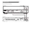
One way to activate the Switched Power
Outlets is to apply power to the AC Line In
Control Cord on the rear panel. This feature
allows you to use a switched outlet on another
component, typically a preamplifier, to turn
on the power to the rest of the system. See
Figure 2. If you do not use this feature, or the
12V Trigger Input, to activate the Switched
Outlets of the RLC-1050, the Control Cord must
be plugged into the Unswitched Outlet
on the RLC-1050 rear panel.
12V Trigger In and
Another way to activate the Switched Outlets
of the RLC-1050 is to apply a turn on volt-
age signal to one of the 12V Trigger In con-
nectors. When a turn on voltage signal is
applied to one of the 12V Trigger In connec-
tors the Switched Outlets of the RLC-1050 are
activated, even if the front panel power but-
ton has not been pressed.
The turn on voltage signal may be AC or DC
and can range from 3 volts to 30 volts. Many
components can provide a turn on voltage trig-
ger signal when they are turned on. Both a
bare wire connector
and a mini-plug type
connector
are provided.
When using the bare wire connector with a
DC trigger signal be sure to maintain proper
polarity. Connect positive to positive and nega-
tive to negative.


