7 English
Switched Power Outlets
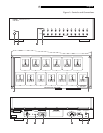
There are 12 switched AC outlets on the rear
panel that are controlled by the RLC-1050.
In addition there is one unswitched outlet. Each
of the switched outlets has separate turn-on
delay and turn-off delay controls. The outlets
on the RLC-1050 are a “universal” type which
will accept virtually any type of power plugs.
NOTE: The RLC-1050 can provide up to
1500 watts of power. All electrical devices
list the amount of power they will draw on
the back panel. Add up the wattage of all
the components that will be connected to the
RLC-1050 to be sure it does not exceed 1500
watts.
Turn-On Delay Controls and
Turn-Off Delay Controls
Each switched outlet of the RLC-1050 has
separate turn-on delay and turn-off delay con-
trols. The delay for each control can be ad-
justed from 1 to 30 seconds. When the con-
trols are turned all the way counterclockwise
the delay is only 1 second. When the con-
trols are turned all the way clockwise the de-
lay is 30 seconds.
By setting the controls so that the system com-
ponents turn on and off in the proper sequence,
turn-on and turn-off thumps noises can be pre-
vented.
Signal sources such as CD players should be
turned on first. Set the Turn-On Delay Con-
trols for these components for 1 second de-
lay. Components such as signal processors
should be turned on next. Set the Turn-On
Delay Control for these components to pro-
vide a somewhat greater turn on delay. Am-
plifiers should be turned on last, and so should
have the greatest amount of turn on delay. That
does not mean that the Turn-On Delay Con-
trol for the amplifier must be at the maximum
setting. A delay of 10-15 seconds may be
enough to prevent turn on noises.
NOTE: Amplifiers can draw large amounts
of power. A high power amplifier can draw
more power than the RLC-1050 can handle.
Do not connect components to the RLC-1050
that will require more than 1500 watts total.
Generally the components should be turned
off in the reverse order they are turned on.
Amplifiers should be turned off first and sig-
nal sources last. Components that have short
turn-on delays should have long turn-off de-
lays. Components that have long turn-on de-
lays should have short turn-off delays.
Power Indicators
The Power Indicators for each switched out-
let light when power is applied to the outlet.
These indicators provide a visual indication
of the sequence in which the various power
outlets are turned on and off.
Unswitched Outlet
The unswitched outlet may be used in one of
two ways. If the Switched Outlets of the
RLC-1050 are not activated with either the
AC Line In Control Cord or the 12V Trigger
In, it must be connected to the Unswitched
outlet. Otherwise the RLC-1050 Switched Out-
lets will not be activated. If one of the two
control systems is used to activate the
RLC-1050 switched outlets, the Unswitched
Outlet may be used to supply power to a com-
ponent that should always be powered.
NOTE: Do not connect a component that
requires more than 400 watts to the
Unswitched outlet.
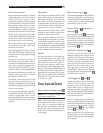
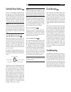
1 second delay 30 second delay
3-5 second delay
23-27 second delay
13-17 second delay
Circuit Breaker
If the components connected to the RLC-1050
draw more power than it can safely deliver,
or if there is a short circuit in one of the power
lines of one of the components, the Circuit
Breaker will be tripped. If this occurs, turn off
the RLC-1050 and check to be sure the total
power requirements of the components con-
nected to the RLC-1050 does not exceed 1500
watts.
If the power requirements of the connected
components is not greater than 1500 watts
the circuit breaker being tripped might indi-
cate a problem in one of the components. Try
the following test to isolate a potentially de-
fective component. First, turn off all the con-
nected components with their built-in power
switches. Turn on the RLC-1050 and activate
the Switched Power Outlets. Then turn on the
components connected to the RLC-1050 one
by one. Turn them on in the same order they
would be turned on by the RLC-1050 – sig-
nal sources first, amplifier last. If the Circuit
Breaker is tripped as soon as a component
is turned on it indicates a problem with that
component.
Troubleshooting
Most difficulties are the result of incorrect con-
nections, or improper control settings. The Main
Power Indicator should be lit whenever the
RLC-1050 is plugged into the wall power outlet,
and the Main Power Switch is pushed. If it does
not light, test the power outlet that the Main
Power cord of the RLC-1050 is plugged into
with another electrical device, such as a lamp.
Be sure the power outlet being used is not con-
trolled by a switch that has been turned off.


