


RS900 Family Installation Guide
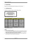
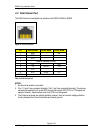
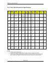
4.2 RJ45 Serial Port
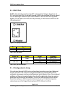
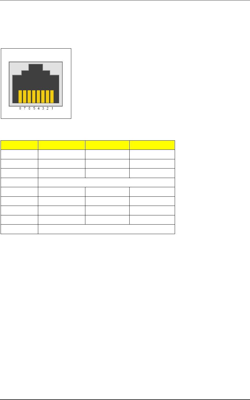
The RJ45 Serial port is selectable via software to be RS232, RS485 or RS422.
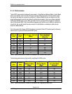
Figure 16: RJ45 Port pin-out
Pin RS232 Mode RS485 Mode RS422 Mode
1 DSR - RX-
2 DCD - -
3 DTR - -
4 Common (Isolated Ground)
5 RX - RX+
6 TX TX/RX + TX +
7 CTS - -
8 RTS TX/RX - TX -
Shield Chassis Ground
Table 10: RJ45 Port pin-out
NOTES:
1. No internal termination is provided.
2. Pins 1, 2, and 3 are connected internally. Pins 7 and 8 are connected internally. The pins are
permanently asserted to 5V so that DTE devices that require DCD, DTR, or CTS signals will
operate. However, hardware flow control via RTS is not recognized.
3. The Common terminals are optically isolated; however, there is transient voltage protection
circuitry between the Common terminals and chassis ground.
Page 29 of 42
© 2008 RuggedCom Inc. All rights reserved. Rev100