


RS900 Family Installation Guide
Page 5 of 42
© 2008 RuggedCom Inc. All rights reserved. Rev100
Table of Figures
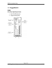
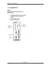
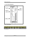
Figure 1 - Front Panel Description ........................................................................................................... 13
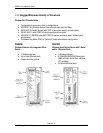
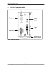
Figure 2 - Bottom Panel Description......................................................................................................... 14
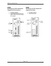
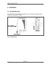
Figure 3 - DIN Rail Mounting ................................................................................................................... 15
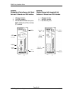
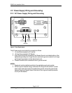
Figure 4 - Power Supply Inputs................................................................................................................. 16
Figure 5 - DC Power supply wiring and grounding diagram ................................................................. 17
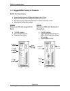
Figure 6 - Failsafe Output Relay............................................................................................................... 18
Figure 7 - Dielectric Strength Testing....................................................................................................... 19
Figure 8 - RS232 Female DCE pin-out ..................................................................................................... 20
Figure 9 - RJ11 port pin-out and LEDs.................................................................................................... 22
Figure 10 - RJ45 port pin-out and LEDs.................................................................................................. 25
Figure 11 - 100FX MTRJ connector ........................................................................................................ 26
Figure 12 - 100FX ST connector .............................................................................................................. 26
Figure 13 - 100FX SC connector .............................................................................................................. 26
Figure 14 - 100FX LC connector.............................................................................................................. 26
Figure 15: DB9 Female DCE Port pin-out ............................................................................................... 28
Figure 16: RJ45 Port pin-out..................................................................................................................... 29
Figure 17: Fiber Serial Interface (ST Connector) ................................................................................... 30
Figure 18: Conceptual recommended RS485 wiring diagram................................................................ 31
Figure 19 - Mechanical Specifications ...................................................................................................... 40
Table of Tables
Table 1 - Status LEDs................................................................................................................................. 13
Table 2 - RS232 Female DCE pin-out....................................................................................................... 20
Table 3 - RJ11 port pin-out ....................................................................................................................... 22
Table 4 - RJ11 port LED description........................................................................................................ 22
Table 5 - Typical Performance on 24 AWG PIC twisted-pair with Universal EoVDSL ports............ 23
Table 6 - Typical Performance on 24 AWG PIC twisted-pair with Long-Reach EoVDSL ports ....... 23
Table 7 - RJ45 port pin-out ....................................................................................................................... 25
Table 8 - RJ45 port LED description........................................................................................................ 25
Table 9: DB9 Female DCE Port pin-out................................................................................................... 28
Table 10: RJ45 Port pin-out ...................................................................................................................... 29
Table 11 - Operating Environment........................................................................................................... 33
Table 12 - Power Supply Specifications.................................................................................................... 33
Table 13 - Failsafe Relay Specification..................................................................................................... 33
Table 14 - Failsafe Relay Isolation............................................................................................................ 34
Table 15 – RJ11 Ethernet over VDSL Port Specifications ..................................................................... 34
Table 16 – RJ45 Ethernet Port Specifications.......................................................................................... 34
Table 17 - Fiber Optic Port Specifications ............................................................................................... 35
Table 18 - Communication Standard Compliance .................................................................................. 36
Table 19 - Wireless Standards Supported................................................................................................ 37
Table 20 - Radio Characteristics............................................................................................................... 37
Table 21 - Channel allocations for IEEE 802.11b/g................................................................................. 38
Table 22: Copper Port Specification......................................................................................................... 39
Table 23: Fiber Optic Port Specification.................................................................................................. 39
Table 24 - Mechanical Specifications........................................................................................................ 40
Table 25 - IEC 61850-3 Type Tests ........................................................................................................... 41
Table 26 - IEEE 1613 Type Tests.............................................................................................................. 42
Table 27 - Environmental Type Tests....................................................................................................... 42