


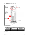
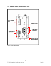
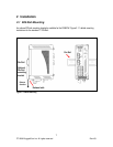
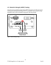
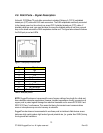
9
2008 RuggedCom Inc. All rights reserved Rev103
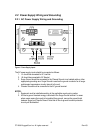
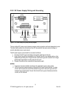
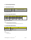
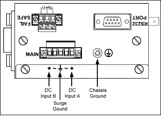
2.2.2 DC Power Supply Wiring and Grounding
Figure 5 - DC Power supply wiring and grounding diagram
The low voltage DC power supply features reverse polarity protection and dual independent inputs.
The latter feature allows the connection of two DC sources with the same nominal voltage to
provide redundant power supply inputs.
The DC power supply inputs should be connected as follows:
1. Connect to the DC inputs according to the polarity markings on the unit.
2. Surge Ground should be connected to the Chassis Ground via a braided cable or other
appropriate grounding wire. Surge Ground is used as the ground conductor for all surge
and transient suppression circuitry internal to the unit.
3. Chassis Ground must be connected to the protective earth.
NOTES:
1. Equipment must be installed according to the applicable country wiring codes.
2. All line-to-ground transient energy is shunted to the Surge Ground terminal. In cases
where users require the inputs to be isolated from ground, remove the ground braid
between Surge and Chassis Ground. Note that all line-to-ground transient protection
circuitry will be disabled.