


19
2007 RuggedCom Inc. All rights reserved Rev100
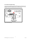
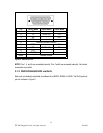
RuggedCom also does not recommended to use these ports to interface to field devices across
distances which could produce high levels of ground potential rise, (i.e. greater than 2500V) during
line to ground fault conditions.
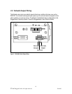
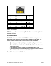
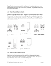
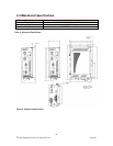
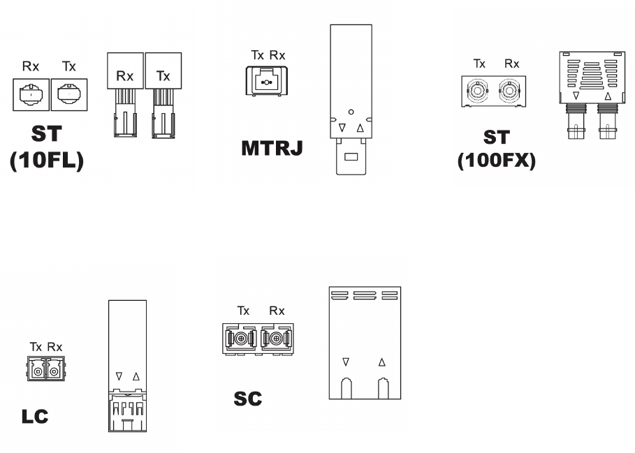
4.2 Fiber Optic Ethernet Ports
Depending on the order code of the product, the RS910W can be equipped with several different
fiber optic ports. The Transmit (Tx) and Receive (Rx) connections of each port must be properly
connected and matched for proper link and operation. The drawings in the following figures show
each fiber optical connector style with a side and top view to allow the user to identify the proper
cable connection orientation.
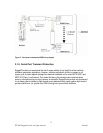
Figure 14: 10FL ST connector
Figure 15: 100FX MTRJ connector
Figure 16: 100FX ST connector
Figure 17: 100FX LC connector
Figure 18: 100FX SC connector
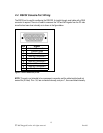
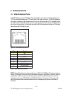
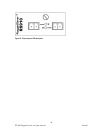
4.3 Ethernet Panel Description
Each Ethernet and Serial port is equipped with one LED that indicates link/activity status
information. The LED will be solid for ports with link, and will blink for activity. The diagram in
Figure 19 highlights the port and the associated link/activity LED.