


Spinpoint M8-DVR OEM Product Manual REV 1.0
50
Some parameters are defined as a string of ASCII characters. For the string “Copyright,” the character ‘C’ is
the first byte, ‘o’ is the 2nd byte, etc. When such fields are transferred, the order of transmission is:
1st character (‘C’) is on bits DD15 through DD8 of the first word
2nd character (‘o’) is on bits DD7 through DD0 of the first word
3rd character (‘p’) is on bits DD15 through DD8 of the second word
4th character (‘y’) is on bits DD7 through DD0
of the second word, etc.
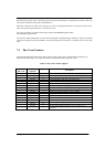
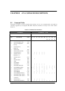
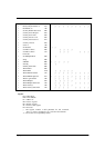
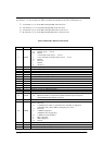
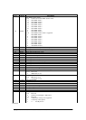
Table 8-5 IDENTIFY DEVICE information
Word
Content
Description
0
0040h
General configuration bit-significant information:
15 0=ATA device, set to 0
14-8 Retired
7 1=removable media device, set to 0
6 1=not removable controller and/or device, set to 1
5-3 Retired
2 Reserved
1 Retired
0 Reserved
1
XXXXh
Number of logical cylinders
2
0
Reserved
3
00XXh
Number of logical heads
4-5
0
Retired
6
003Fh
Number of logical sectors per logical track
7-8
0
Reserved for CFA
9
0
Retired
10-19
Serial number (20 ASCII characters, 0 = not specified)
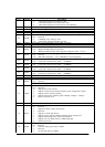
20
0000h
Retired
21
4000h
Retired
22
0004h
Number of ECC bytes (Device native length is selected via set feature command.)
23-26
Firmware revision (8 ASCII characters)
27-46
Model number (40 ASCII characters)
47
8010h
15-8 80h
7-0 Maximum number of sectors that shall be transferred per interrupt on
READ/WRITE MULTIPLE commands
48
4000h
Reserved
49
2F00h
Capabilities
15-14 Reserved
13 1=Standby timer values as specified in this standard are supported
0=Standby timer values shall be managed by the device
12 Reserved
11 1=IORDY supported
0=IORDY may be supported
10 1=IORDY may be disabled
9 LBA supported
8 DMA supported
7-0 Retired
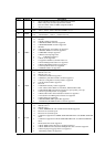
50
4000h
Capabilities
51
0200h
PIO data transfer cycle timing mode (Obsolete)
52
0200h
DMA data transfer cycle timing mode (Obsolete)
53
0007h
15-3 Reserved