


Memory and Microprocessor Configuration 5–7
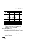
Increasing Microprocessor Speed
3. Place the GRAFOIL pad on the gold-plated slug surface and align it with
the threaded studs.
b. Attach the microprocessor heat sink. The heat-sink material is clear anod-
ized, hot-water-sealed, 6061-T6 aluminum. The nut material is 2011-T3 alu-
minum (this grade is critical). Perform the following steps to attach the heat
sink:
1. Observe antistatic precautions.
2. Align the heat-sink holes with the threaded studs on the ceramic package.
3. Handle the heat sink by the edges and lower it onto the chip package,
taking care not to damage the stud threads.
4. Set a calibrated torque driver to 20 in-lbs, ±2 in-lbs (2.3 Nm, ±0.2 Nm).
The torque driver should have a mounted 7/16-inch socket.
5. Insert a nut into the 7/16-inch socket, place on one of the studs, and
tighten to the specified torque. Repeat for the second nut.
6. If the sink/chip/fan clip is used, properly install it by positioning it over
the assembly and hooking its ends around the ZIF socket retainers.
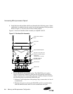
c. Attach the heat-sink fan assembly:
1. Place the fan assembly on top of the heat sink, aligning the fan mounting
holes with the corresponding threaded heat-sink holes. Align the fan so
that the fan power/sensor wires exit the fan closest to connector J35 (see
Figure 2–1). Fan airflow must be directed into the heat sink (fan label
facing down toward the heat sink).
2. Place the fan guard on top of the fan. Orient the guard so that the corner
mounting areas lay flush against the heat sink.
3. Secure the fan and fan guard to the heat sink with four 6-32
X 0.875-inch
screws.
4. Plug the fan power/sensor cable into connector J35.
Important: When installing the microprocessor, you must change the frequency of
its clock output by setting the CPU speed selection jumpers (J28 Option
1~4), as described in Section 3.1.