


Rev. 1.00
-18-
BCD-1000 Series
English
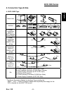
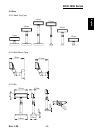
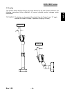
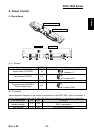
6-2 Serial pin Connection
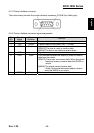
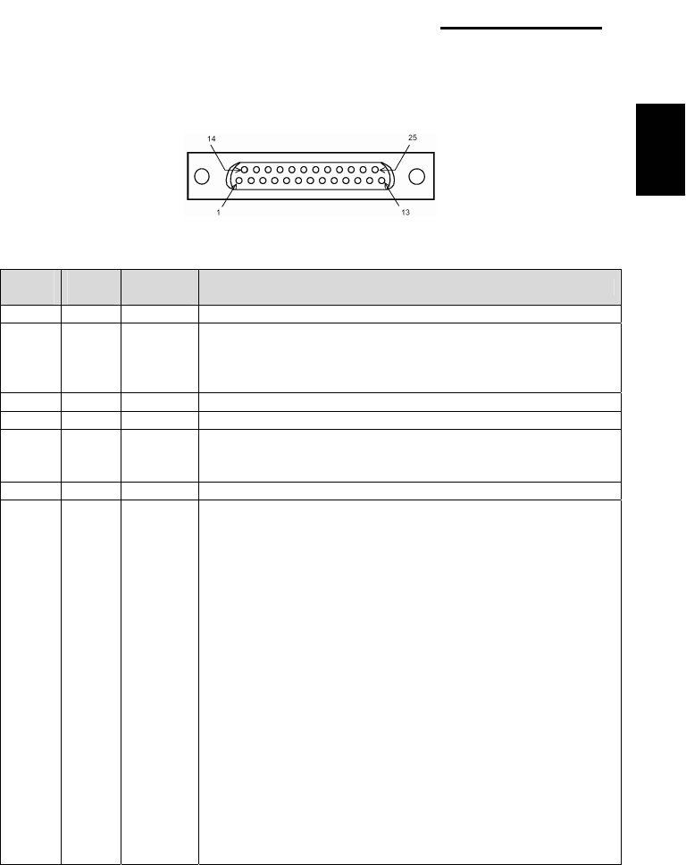
6-2-1 Host interface connector
The option stand provides the host interface connector (D-SUB 25 pin Female type).
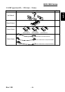
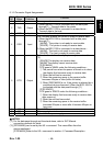
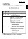
6-2-2 Host interface connector signal assignments
Pin
NO
Signal
Name
Signal
Direction
Function
1 FG - Frame ground
2 TXD Output
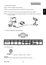
1) When the BDC-1000 is connected when a passthrough
connection :Transmit data to the host from the printer
2) When the BDC-1000 is connected as a stand-alone :
Transmit data to the host from the DM
3 RXD Input Receive data from the host (host → DM)
4(*1) RTS Output Same as DTR
6(*2) DSR Input
Indicates whether the host is ready to receive data.
[SPACE] The host is ready to receive data.
[MARK] The host is not ready to receive data.
7 GND - Signal ground
20(*1) DTR Output
This indicates whether the display is ready to receive data.
[SPACE] The display can receive data.
[MARK] The display cannot receive data.
[DTR MARK]
DTR goes to MARK under the following conditions :
① The period from when the power is turned on to
when the display first becomes ready to receive data.
② When the self-test is executed.
③ When the remaining space in the receive buffer
becomes 40bytes or less (buffer-full state).
④ When [DSR MARK] is on, if the printer is selected
by a peripheral device command.
[DTR SPACE]
DTR goes to SPACE under the following conditions :
① When the display first becomes ready to receive
data after power-on.
② When the self-test has ended.
③ when the remaining space in the receive buffer
becomes 50bytes or more after it became
40bytes or less once.
NOTES※
(*1) Make sure to use either one of the RTS or the DTR terminal. Otherwise,
the built-in RS-232 driver IC may be broken.