


Use control bar after selecting ÒH-SIZEÓ in left
menu to adjust the horizontal size of the display
pattern to 306 mm (17Ó) and 267 mm (15Ó).
(Tolerance: ± 3 mm.)
If ÒH-SIZEÓ is not enough to adjust it, select
ÒSIZE B+Ó by turns.
4-2-4 (b) VERTICAL SIZE ADJUSTMENT
CONDITIONS
Scanning frequency: 68 kHz/85 Hz (17Ó)
54 kHz/85 Hz (15Ó)
Display image: Crosshatch pattern
Brightness: Maximum
Contrast: Maximum
Use control bar after selecting ÒV-SIZEÓ in left
menu to adjust the vertical size of the display
pattern to 230 mm (17Ó) and 200 mm (15Ó).
(Tolerance: ± 3 mm.)
4-2-4 (c) HORIZONTAL POSITION ADJUSTMENT
CONDITIONS
Scanning frequency: 68 kHz/85 Hz (17Ó)
54 kHz/85 Hz (15Ó)
Display image: Crosshatch pattern
Use control bar after selecting ÒH-POSITIONÓ in
left menu to center the horizontal image on the
raster.
4-2-4 (d) VERTICAL POSITION ADJUSTMENT
CONDITIONS
Scanning frequency: 68 kHz/85 Hz (17Ó)
54 kHz/85 Hz (15Ó)
Display image: Crosshatch pattern
Use control bar after selecting ÒV-POSITIONÓ in
left menu to center the vertical image on the
raster.
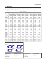
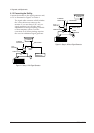
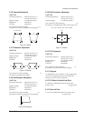
4-2-5 Linearity
Linearity affects the symmetry of images as they
appear on the screen. Unless each row or column
of blocks in a crosshatch pattern is of equal size,
or within the tolerances shown in Tables 4-2 and
4-3, an image appears distorted, elongated or
squashed.
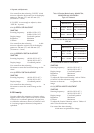
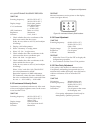
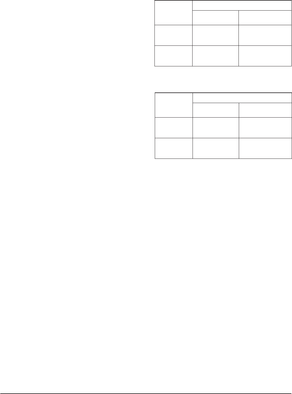
Table 4-2. Standard Modes Linearity: 640x480/75Hz,
800x600/85Hz and 1024x768/85Hz
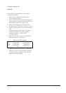
Table 4-3. Other Modes Linearity: VGA, SVGA, XGA,
MAC, etc.
4-2-5 (a) HORIZONTAL LINEARITY ADJUSTMENT
CONDITIONS
Scanning frequency: 68 kHz/85 Hz (17Ó)
54 kHz/85 Hz (15Ó)
Display image: Crosshatch pattern
Brightness: Maximum
Contrast: Maximum
To adjust the Horizontal Linearity, refer to Tables
4-2 and 4-3 for the tolerance range.
Increase or decrease H_LIN to optimize the
image.
4-2-5 (b) VERTICAL LINEARITY ADJUSTMENT
CONDITIONS
Scanning frequency: 68 kHz/85 Hz (17Ó)
54 kHz/85 Hz (15Ó)
Display image: Crosshatch pattern
Brightness: Maximum
Contrast: Maximum
To adjust the Vertical Linearity, refer to Tables 4-2
and 4-3 for the tolerance range.
Use control bar after selecting ÒV-LINEARITY
BALÓ in left menu to optimize the image.
4 Alignment and Adjustments
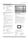
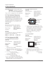
4-4 DP15H*/DP17L*
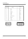
Figure 4-5. Pinbalance
4 : 3
5 : 4
Horizontal: 17.8~20.5
Vertical : 17.8~20.5
Horizontal: 16.7~19.2
Vertical : 17.8~20.5
Supported Timing Mode
Each block (10 %)
Difference between
adjacent blocks (5 %)
Horizontal: Less than 0.96 mm
Vertical : Less than 0.96 mm
Horizontal: Less than 0.90 mm
Vertical : Less than 0.96 mm
4 : 3
5 : 4
Horizontal: 18.2~20.1
Vertical : 18.2~20.1
Horizontal: 17.1~18.9
Vertical : 18.2~20.1
Standard Modes Linearity
Each block (10 %)
Difference between
adjacent blocks (4 %)
Horizontal: Less than 0.77 mm
Vertical : Less than 0.77 mm
Horizontal: Less than 0.72 mm
Vertical : Less than 0.77 mm