


5 Troubleshooting
DP15H*/DP17L* 5-9
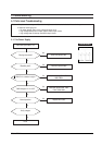
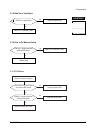
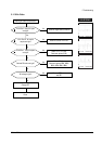
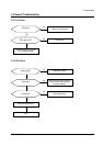
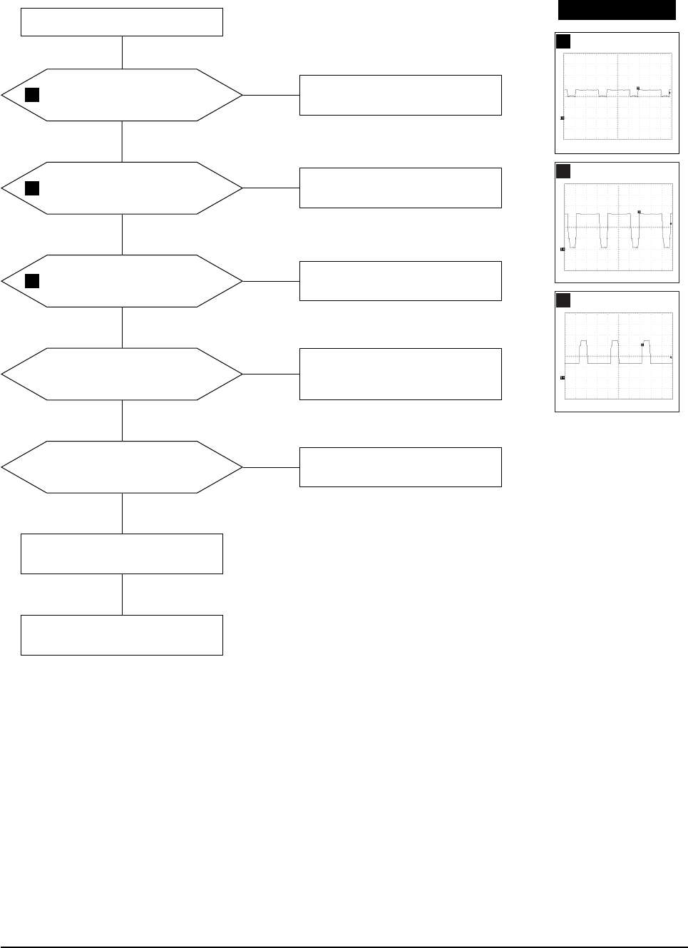
5-1-16 No Video
IC101 Pins 5, 8 and 10 inputs
are right?
IC101 Pins 21, 24 and 26
outputs are right?
Check I
2
C bus and +12 V line.
Yes
Yes
No
Check the signal cable connection.
No
IC103 Pins 1, 2 and 3 outputs
are right?
Check +12 V, +72 V line.
Check and replace IC103.
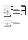
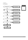
Yes
No
Cathode DC levels are right?
Check +72 V line.
Check and replace QR01, QR02,
QG01, QG02, QB01, QB02.
Yes
No
G2 voltage is right?
Check G2 wire, CRT Socket board,
and FBT.
Change CRT.
Yes
Done.
No
Check signal cable and connection.
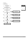
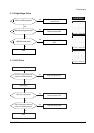
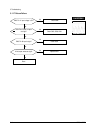
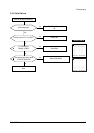
WAVEFORMS
15
16
17
15
1.00 V (IC101, #5, 8, 10)
CH1 P-P = 1.00V CH1 RMS = 2.452V
16
1.00 V (IC101, #21,24,26)
CH1 P-P = 1.00V CH1 RMS = 2.792V
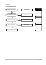
17
20.0 V (IC103, #1, 2, 3)
CH1 P-P = 20.0V CH1 RMS = 40.52V