


5 Troubleshooting
DP15H*/DP17L* 5-11
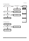
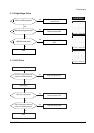
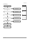
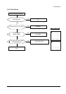
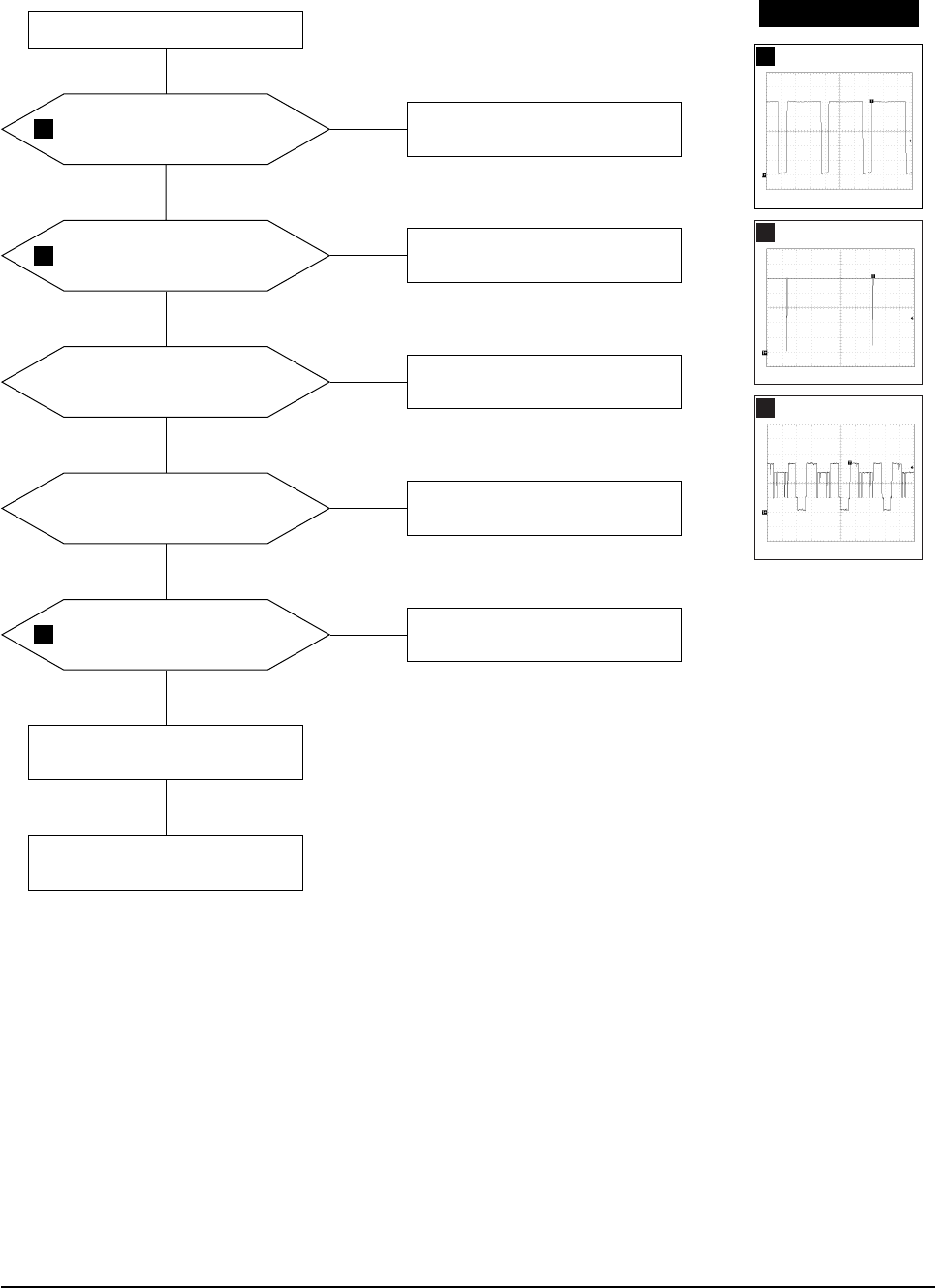
5-1-18 OSD Failure
IC104 Pin 6 input is right?
IC104 Pin 17 input is right?
Check and replace Q101.
Check CN102 Pin 8.
Yes
Yes
No
Check and replace Q102.
Check CN102 Pin 14.
No
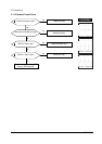
IC104 Pins 7 and 8 inputs are
right?
Check IC201 Pins 41 and 42.
Yes
No
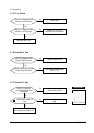
IC104 Pins 12, 13 and 14
outputs are right?
Check and replace IC104.
No
No
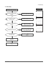
IC101 Pins 21, 24 and 26
outputs are right?
Check and replace IC101.
Check and replace IC103.
Yes
Done
No
Check CN104 and connector Ass’y.
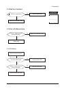
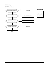
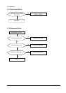
WAVEFORMS
19
20
21
19
1.00 V (IC104, #6)
CH1 P-P = 1.00V CH1 RMS = 4.516V
20
1.00 V (IC104, #17)
CH1 P-P = 1.00V CH1 RMS = 5.024V
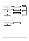
21
1.00 V (IC101, #21.24.26)
CH1 P-P = 1.00V CH1 RMS = 2.580V