


GB-7
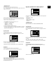
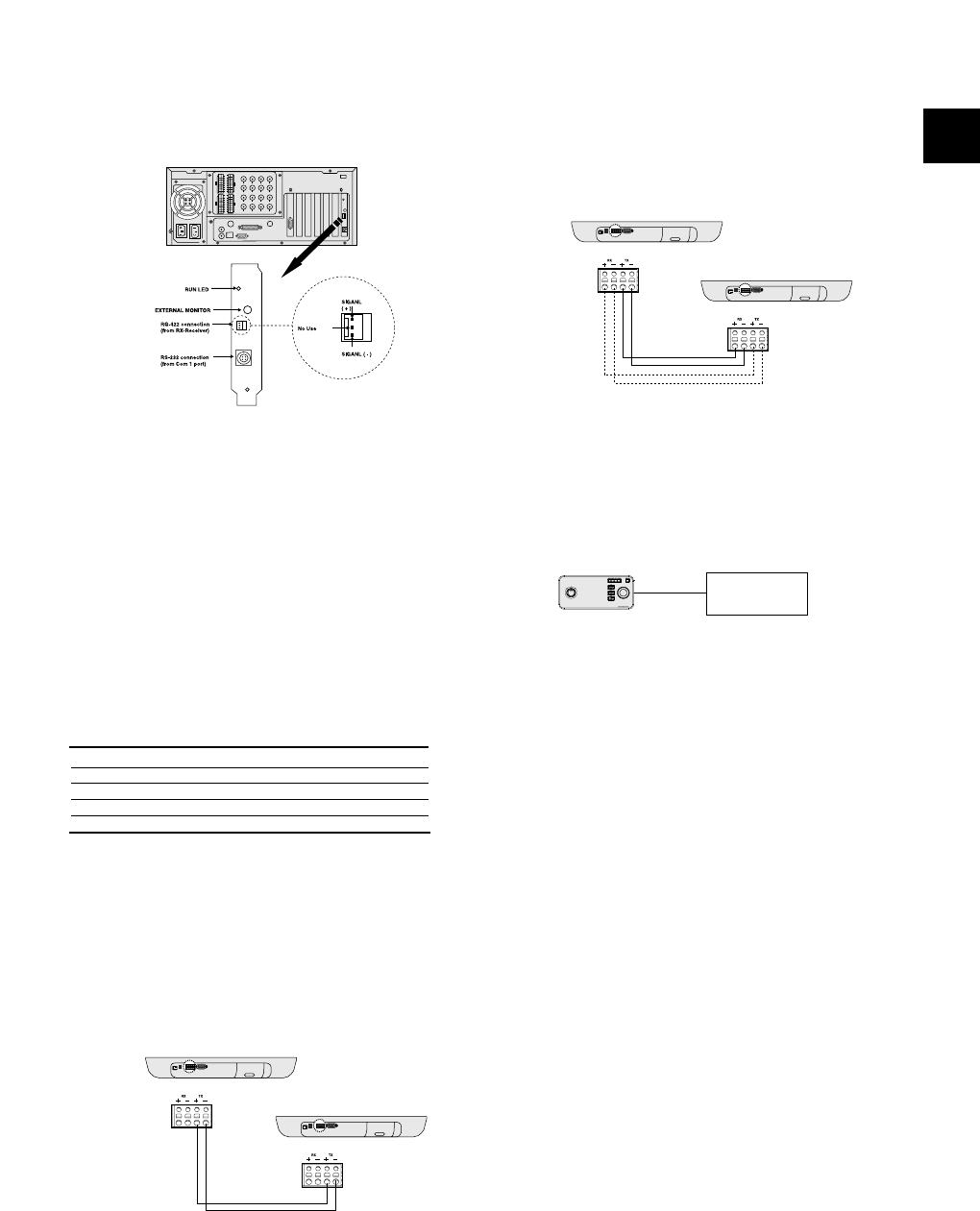
7) Connecting PC based DVR
(Applicable to the SPR Smart View V2.3 over)
- Connect SSC-2000 through the RS-485 port in the back of PC BASED
DVR.
- Connect SIGNAL (+) in the RS-485 port of PC BASED DVR with Tx (+)
of SSC-2000.
- Connect SIGNAL (-) in the RS-485 port of PC BASED DVR with Tx (-)
of SSC-2000.
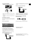
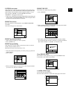
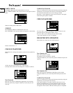
Connecting PC by RS-232
Connect a PC in which a terminal emulation program is installed to
update the S/W of this equipment. Here, you may use the RS-232C
for connection.
RS-232C Port(D-SUB 9PIN)
• Please refer to “RS-232 Communication Setup (GB-13)” of “Chapter 5.
Menu Setup” for RS-232 communication setup.
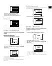
Connecting Other System Keyboard
• It is possible to connect and use max. 32 keyboards simultaneously.
• Refer to the “ADDRESS SET” part in “RS-232 Communication Setup
(GB-13)” of “Chapter 5. Menu Setup” for the setting of keyboard
communication.
• Do not use together with the SSC-1000 because it is different with the
SSC-1000 in communication method.
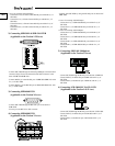
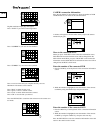
1) In case of connecting with Half Duplex
- Connect the Tx (+) of SSC-2000 port with the Tx (+) of another SSC-2000.
- Connect the Tx (-) of SSC-2000 RS-485 port with the Tx (-) of another
SSC-2000.
2) In case of connecting with Full Duplex
- Connect the Tx (+) of SSC-2000 with the Rx (+) of another SSC-2000.
- Connect the Tx (-) of SSC-2000 with the Rx (-) of another SSC-2000.
- Connect the Rx (+) of SSC-2000 with the Tx (+) of another SSC-2000.
- Connect the Rx (-) of SSC-2000 with the Tx (-) of another SSC-2000.
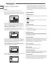
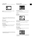
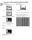
Basic System Diagram of SSC-2000
1) One Keyboard to One Device
2) One Keyboard to Multiple Device (“Daisy-Chain” Type Wiring)
3) Multiple Keyboards to Multiple Device
(“Daisy-Chain” Type Wiring)
• Do not use together with the SSC-1000 because it is different with the
SSC-1000 in communication method.
When using the system by connecting with SCC-931T Version 1.4, make the
address of devices connected to the system different.
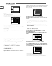
RS-232C 9PIN(Connector Arrangement)
PIN NUMBER PIN SPECIFICATIONS
2 TXD (TRANSMITTED DATA)
3 RXD (RECEIVED DATA)
5 SG (SIGNAL GROUND)
1, 4, 6~9 NO CONNECTION