


360 Herndon Parkway
Suite 1400
Herndon, VA 20170
http://www.rheintech.com
SanDisk Corporation Page 9 of 17
DoC Report
2006137
04/27/07
4 CONDUCTED EMISSIONS
4.1 SITE AND TEST DESCRIPTION
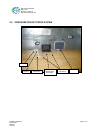
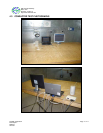
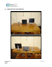
The power line conducted emission measurements were performed in a Series 81 type shielded enclosure
manufactured by Rayproof. The EUT was assembled on a wooden table 80 centimeters high. Power was fed to
the EUT through a 50 ohm /50 microhenry Line Impedance Stabilization Network (EUT LISN). The EUT LISN
was fed power through an A.C. filter box on the outside of the shielded enclosure. The filter box and EUT LISN
housing are bonded to the ground plane of the shielded enclosure. A second LISN, the peripheral LISN,
provides isolation for the EUT test peripherals. This peripheral LISN was also fed A.C. power. A metal power
outlet box, which is bonded to the ground plane and electrically connected to the peripheral LISN, powers the
EUT host peripherals.
The spectrum analyzer was connected to the A.C. line through an isolation transformer. The 50-ohm output of
the EUT LISN was connected to the spectrum analyzer input through a Solar 7 kHz high-pass filter. The filter is
used to prevent overload of the spectrum analyzer from noise below 7 kHz. Conducted emission levels were
measured on each current-carrying line with the spectrum analyzer operating in the CISPR quasi-peak mode (or
average mode if applicable). The analyzer's 6 dB bandwidth was set to 9 kHz. No video filter less than 10 times
the resolution bandwidth was used. Average measurements are performed in linear mode using a 10 kHz
resolution bandwidth, a 1 Hz video bandwidth, and by increasing the sweep time in order to obtain a calibrated
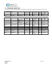
measurement. The range of the frequency spectrum to be investigated is specified in FCC Part 15. The highest
emission amplitudes relative to the appropriate limit were measured and have been recorded in this report.