


SanDisk uSSD 5000 Product Manual
© 2008 SanDisk® Corporation 5 October 2008, Document no. 80-36-03353
1.3 Scope
This document describes the key features and specifications of the uSSD 5000,
as well as the information required to interface this product to a host system.
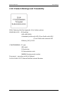
1.3.1 Technology Independence
To write or read a sector (or multiple sectors), the host computer software
simply issues a Read or Write command to the module.
This command contains the address and the number of sectors to write/read.
The host software then waits for the command to be completed.
The host software does not participate in the details of how the flash memory
is erased, programmed or read. This is extremely important as flash devices
are expected to increase in complexity in the future. Because the uSSD 5000
uses an intelligent on-board controller, the host system software will not need
to be changed as new flash memory evolves. As such, systems that support
uSSD 5000 now will be able to access future SanDisk Modules built with new
flash technology without any need to update or change the host software.
1.3.2 Defect and Error Management
The uSSD 5000 contains a sophisticated defect and error management
system.
If necessary, the Module will rewrite data from a defective sector to a good
sector. This is completely transparent to the host and does not consume any
user data space.
The uSSD 5000 soft error rate specification is much better than the magnetic
disk drive specification.
In the extremely rare case that a read error does occur, the uSSD 5000 has
innovative algorithms to recover the data by using hardware on-the-fly Error
Detection Code/Error Correction Code (EDC/ECC), based on a BCH algorithm.
These defect and error management systems, coupled with solid state
construction, give the SanDisk uSSD 5000 unparalleled reliability.
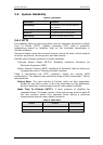
1.3.3 Wear-leveling
Wear-leveling is an inherent part of the erase-pooling functionality of the
SanDisk uSSD 5000, using NAND memory.
Advanced features of dynamic and static wear-leveling and automatic block
management are used to ensure high data reliability and maximize flash life
expectancy.
1.3.4 Bad Block Management
Bad blocks are occasionally created during the lifecycle of a flash component,
in a phenomenon called dynamic bad block accumulation. These bad blocks
must be dynamically marked and replaced to prevent read/write failures.
When a bad block is detected, the embedded bad block mapping algorithm
maps out the block, which is then no longer used for storage.