


Unit 3: Installation
SATO GT4xxe Series Operator Manual PN 9001138A Page 3-11
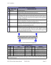
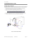
ACCESSORIES INSTALLATION
EXTERNAL SIGNAL CONNECTOR
This connector permits the interface of an external source with the printer for the purpose of
regulating print actiivity to coincide with those external requirements (i.e.: production flow, etc.).
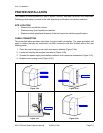
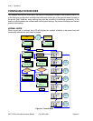
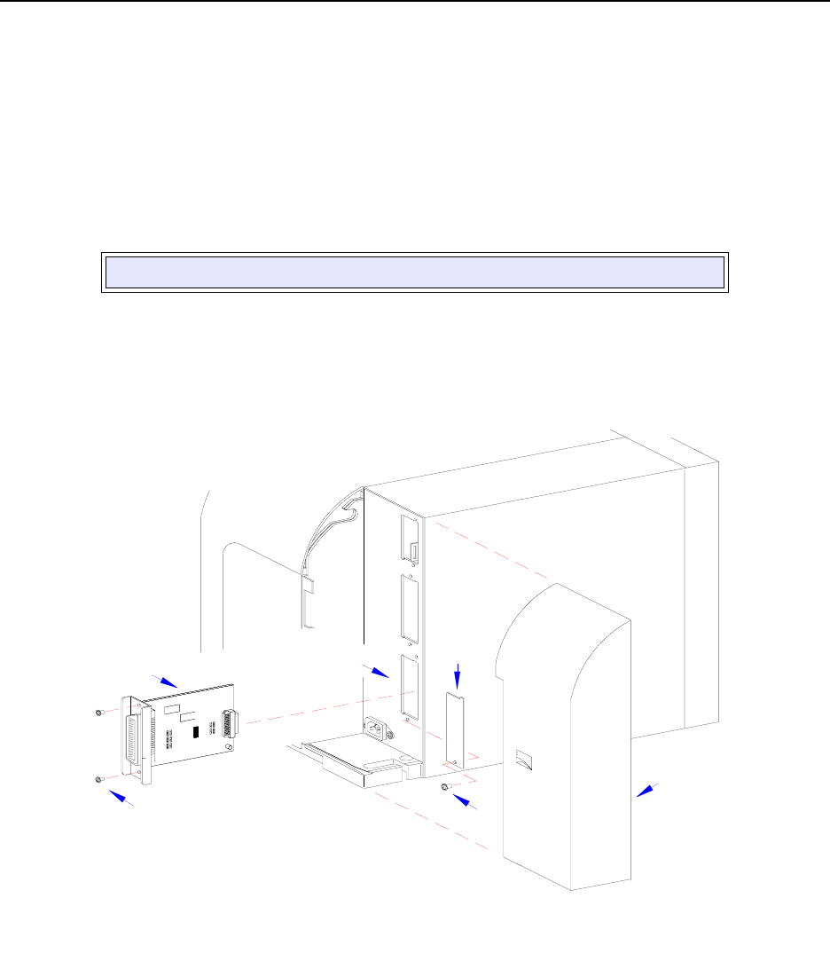
1 Disconnect power supply cord and remove the rear housing cover (1, Figure 3-6).
2 Remove screw (2) and plate (3) as required to expose the EXT port.
3 Remove two screws (4) and withdraw existing board (5) from frame (6) as required.
4 Insert external signal board (5) into slot in frame (6) and secure using two screws (4).
5 Connect the interface cord, power cord, and reinstall rear housing covers.
Figure 3-6, External Signal Connector
NOTE: The above step only applies if replacing an exisiting board.
1
I
E
E
E
1
2
8
4
+
R
S
B
O
A
R
D
2
I
E
E
E
1
2
8
4
+
R
S
B
O
A
R
D
3
4
5
6