


< previous | home | next >
EZ Manual: XL4xxe 4
Barcode SATO International Pte Ltd
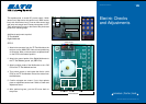
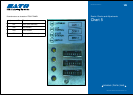
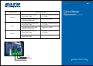
Electric Checks and Adjustments
Chart 2
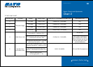
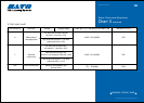
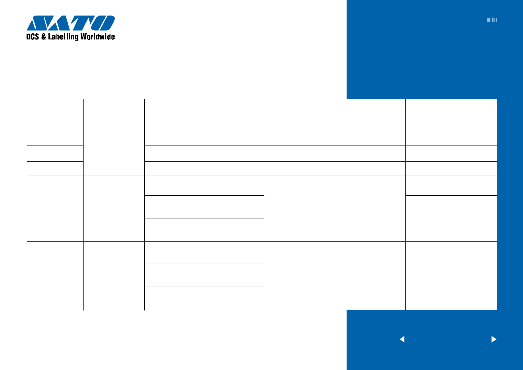
TP TEST POINT CHART
Dial test point Comment Voltage Voltage Range Check pin on TP Test Module and Main PCB Adjustment to VR
0 +5.0 VDC +4.8V to +5.2V CH3A(+5.0V) - CH1A(GND) N/A
1
DC power Supply
+2.0 VDC +1.9V to +2.1V CH4A(+2.0V) - CH1A(GND) N/A
2 +3.3 VDC +3.1V to +3.5V CH5A(+3.3V) - CH1A(GND) N/A
3 +24.0 VDC +23.5V to +24.5V CH6A(+24.0V) - CH1A(GND) N/A
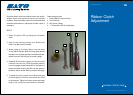
VR8 and VR2
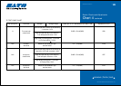
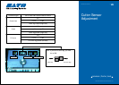
4 I-Mark Sensor Level CH1B(+8.4V) - CH1A(GND)
5 CH2B - CH1A(GND) VR1 and VR9 (Fine adjustment)
Low level (Set the no eye-mark point
in the sensor’s) = Less than +0.5V
High level (Set the eye-mark in the sensor’s)
= Low level plus more than +0.9V
High level (with eye-mark point) - Low level
(without eye-mark point) = +0.9V
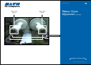
Low level (Set the label backing liner or centre
hole tag in the sensor’s)
= Less than +0.5V
High level (Set the label and tag in the
sensor’s) = Low level plus more than +0.1V
High level (printing point) -
Low level (gap point) = +1.0V
(VR2 is used for adjusting the
light reception flow. If there is
difference between the high and
low level, adjust VR2 to allow
some level difference.)
Gap/Tag Center
Hole Sensor Level