


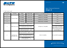
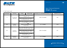
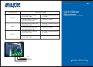
8 R corner hole CH5B - CH1A(GND) VR6
sensor level
N/A R corner TP2 - TP4(GND) VR10
slice level
N/A Jump hole CH6B - CH1A(GND) VR7
sensor level
N/A Jump hole TP3 - TP4(GND) VR11
slice level
< previous | home | next >
EZ Manual: XL4xxe 6
Barcode SATO International Pte Ltd
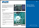
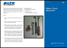
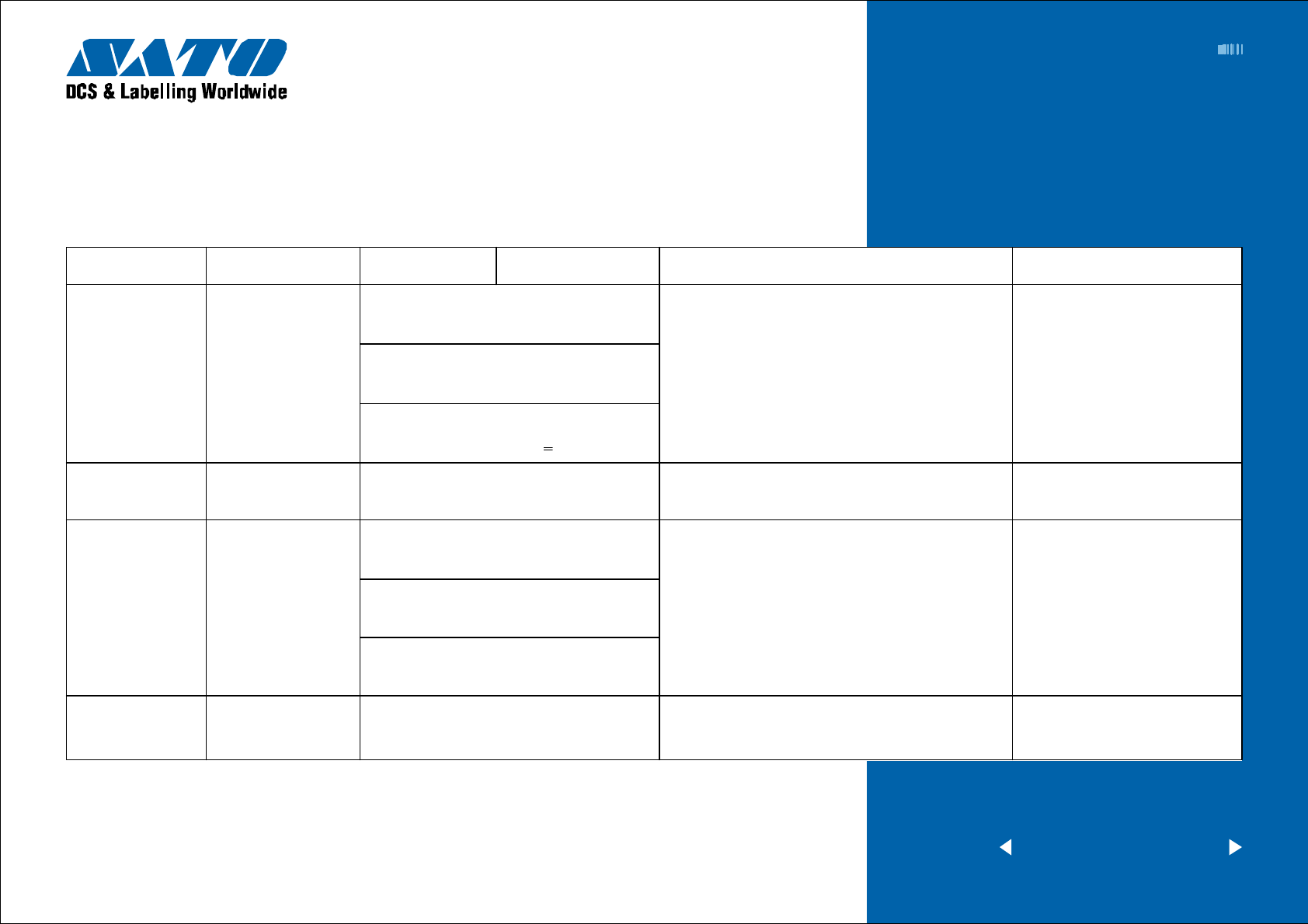
Electric Checks and Adjustments
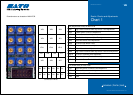
Chart 4 continued
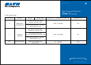
TP TEST POINT CHART
Dial test point Comment Voltage Voltage Range Check pin on TP Test Module and Main PCB Adjustment to VR
Low level (Set the R corner in the sensor’s)
: Less than +0.5V
High level (Set the tag in the sensor’s)
: Low level plusmore than +2.0V
(High level on printing point) - (Low level
on R corner point)
>
+2.0V
Middle of level between high
and low levels
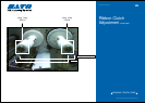
Low level (Set the jumphole in the sensor’s)
: Less than +0.5V and more than +0.2V
High level (Set the tag in the sensor’s)
: Low level plus more than +2.0V
High level (printing point) - Low level
(R corner point) +2.0V
Middle of level between high
and low levels