


WebSTAR Model DPC2100 and EPC2100 Cable Modem User’s Guide
22
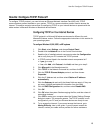
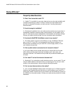
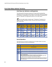
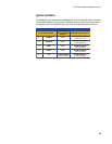
Front Panel Status Indicator Functions
Initial Power Up, Calibration, and Registration
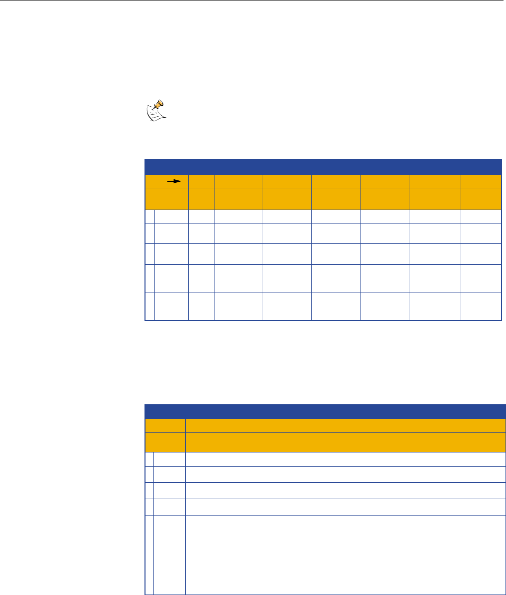
The following chart illustrates the sequence of steps and the corresponding
appearance of the front panel status indicators on the cable modem during power
up, calibration, and registration on the network. Use this chart to troubleshoot the
power up, calibration, and registration process of your cable modem.
After the cable modem completes step 7 (Registration Completed), the
modem proceeds immediately to step 8. See the chart in Normal Operations,
next in this section.
Front Panel LED Status Indicators During Initial Power Up, Calibration, and Registration
Front Panel LED Status Indicators During Initial Power Up, Calibration, and Registration
Step
1 POWER
Front Panel
Indicator
2
3
1
ON
Self
Test
7
ON
Registration
Completed
2
ON
Downstream
Scan
3
ON
Downstream
Signal Lock
4
ON
Ranging
5
ON
Requesting
IP Address
5PC ON ON
ON
or
BLINKING
ON
or
BLINKING
ON
or
BLINKING
ON
or
BLINKING
ON
or
BLINKING
6
ON
Registering
4 CABLE ON ON
SLOW
BLINKING
1 blink
MOMENTARY
ON
OFF
BLINKING
2 blinks
BLINKING
4 blinks
RECEIVE ON ONOFF
OCCASIONAL
BLINKING
OCCASIONAL
BLINKING
OCCASIONAL
BLINKING
OCCASIONAL
BLINKING
SEND ON ONOFF OFF
OCCASIONAL
BLINKING
OCCASIONAL
BLINKING
OCCASIONAL
BLINKING
T10683
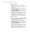
Normal Operations
The following chart illustrates the appearance of the cable modem front panel
LED status indicators during normal operations.
Front Panel LED Status Indicators During Normal Operations
Front Panel LED Status Indicators During Normal Operations
Step
1 POWER
Front Panel
Indicator
ON
Normal Operations
5PC
2 RECEIVE
4 CABLE
ON - When a single device is connected to either the Ethernet or USB port and no data is being
sent to or from the modem.
BLINKS - LED blinks when only one Ethernet or USB device is connected and
data is being transferrd between the consumer premise equipment (CPE) and the cable modem.
OFF - When no devices are connected to either the Ethernet or USB ports.
Note: With both Ethernet and USB devices connected to the modem at the same time, when data is being
transferred through only one of the devices (Ethernet or USB), the indicator will illuminate continuously.
Whenever data is being sent through both data ports (Ethernet and USB) simultaneously, the indicator will
blink as described above.
BLINKS - To indicate data is being transferred between the modem and the network.
3 SEND BLINKS - To indicate data is being transferred between the modem and the network.
ON
8
T10969