ROSA EM - Element Management System
4
Specifications - continued
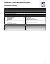
Remote Control and Configuration Ports - continued
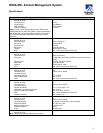
Analog Inputs
Number of ports
Connector type
Contacts per port
Input range
Type
Resolution
Input impedance
8
Female, 25 pin Sub-D
2
0 to +15 V by default, configurable to 0 to +60 V
Differential input
8 bit (55 mV step with 15 V input range, 250 mV step with
60 V input range)
> 100 kΩ
Analog Outputs
Number of ports
Connector type
Contacts per port
Output voltage range
Resolution
Output impedance
2
Female, 25 pin Sub-D
2
0 to +10 V
8 bit (40 mV step)
1 kΩ
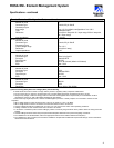
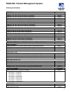
Craft Interface
Number of ports
Connector type
Pin layout
Physical layer
Baud rate
ESD
1
Male, 9 pin Sub-D
Standard DTE
RS-232
Up to 38.4 kbaud (default 19.2 kbaud)
Max. 15 kV
Keyboard and Mouse
Number of ports
Connector type
Pin layout
Physical layer
ESD
2
PS/2
Standard PS/2
RS-232
Max. 15 kV
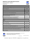
Monitor
Number of ports
Connector type
Pin layout
Resolution
1
DB15H
VGA
Up to 1024 x 768 (SVGA)
(*) Note concerning Safety Extra-Low Voltage (SELV) Circuit Warning
To avoid electric shock and in order to comply with the product’s regulatory safety compliance certifications:
• Do not connect any I/O, signal or communication port to circuits falling beyond the requirements for SELV circuits
• Always verify voltage, current and energy levels of connected circuits against SELV requirements (for a full definition of SELV
requirements, refer to UL, EN or IEC 60950 standards for limit values).
• Ensure that only ‘Digital Input Ports’, Galvanic Isolated Digital Input Ports’ or ‘Relay Outputs’ are connected to outdoor circuits.
Important:
• SELV voltage limits for indoor connections are < 60 V DC (or peak) or < 42.4 V AC RMS.
• SELV voltage limits for outdoor connections are lower than those for indoor connections.
• Outdoor voltages should be no greater than 15 Vrms, 21.2 Vpk, and 30 V DC under normal operating conditions.
• Cabling of outdoor circuits must be shorter than 140 feet or 42 meters.
• In all cases it is needed to protect outdoor cabling by means of a Primary Surge Protector at the position where the wiring enters the
building.
• Outdoor cabling should be routed away and spaced with adequate clearances from power and lighting conductors.
• For installations in the United States, refer to the appropriate sections in the National Electrical Code (NEC).
• For installations in other countries, ensure that the installation complies with the National requirements taking in account the above-
mentioned recommendations.


