


CHEETAH 15K.7 SAS PRODUCT MANUAL, REV. F 37
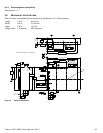
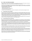
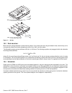
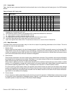
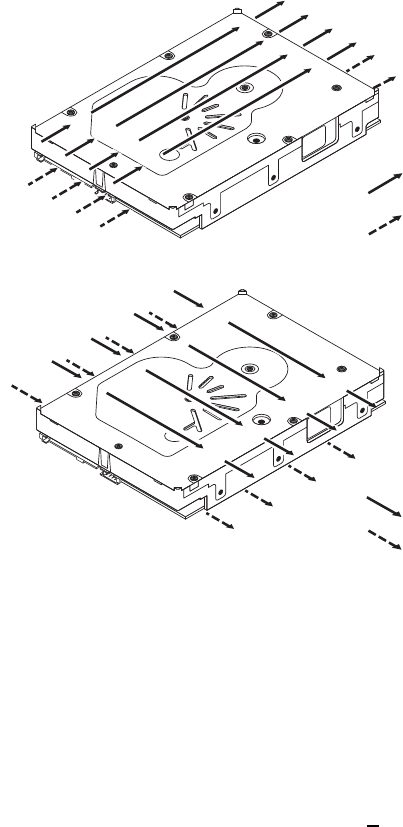
Figure 11. Air flow
10.3 DRIVE MOUNTING
Mount the drive using the bottom or side mounting holes. If you mount the drive using the bottom holes, ensure that you do
not physically distort the drive by attempting to mount it on a stiff, non-flat surface.
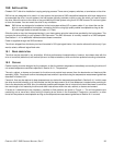
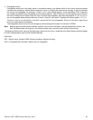
The allowable mounting surface stiffness is 80 lb/in (14.0 N/mm). The following equation and paragraph define the allowable
mounting surface stiffness:
where K is the mounting surface stiffness (units in lb/in or N/mm) and X is the out-of-plane surface distortion (units in inches
or millimeters). The out-of-plane distortion (X) is determined by defining a plane with three of the four mounting points fixed
and evaluating the out-of-plane deflection of the fourth mounting point when a known force (F) is applied to the fourth point.
10.4 GROUNDING
Signal ground (PCBA) and HDA ground are connected together in the drive and cannot be separated by the user. The
equipment in which the drive is mounted is connected directly to the HDA and PCBA with no electrically isolating shock
mounts. If it is desired for the system chassis to not be connected to the HDA/PCBA ground, the systems integrator or user
must provide a nonconductive (electrically isolating) method of mounting the drive in the host equipment.
Increased radiated emissions may result if you do not provide the maximum surface area ground connection between
system ground and drive ground. This is the system designer’s and integrator’s responsibility.
Above unit
Under unit
Note. Air flows in the direction shown (back to front)
or in reverse direction (front to back)
Above unit
Under unit
Note. Air flows in the direction shown or
in reverse direction (side to side)
KxX=F< 15lb = 67N