


30 Pipeline HD SATA Product Manual, Rev. F
Serial ATA Interface www.seagate.com
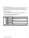
Notes:
1. All pins are in a single row, with a 1.27mm (0.050”) pitch.
2. The comments on the mating sequence apply to the case of backplane blindmate connector only. In this
case, the mating sequences are:
• the ground pins P4 and P12.
• the pre-charge power pins and the other ground pins.
• the signal pins and the rest of the power pins.
3. There are three power pins for each voltage. One pin from each voltage is used for pre-charge when installed
in a blind-mate backplane configuration.
4. All used voltage pins (V
x
) must be terminated.
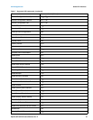
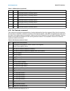
4.3 Supported ATA commands
The following table lists Serial ATA standard commands that the drive supports.
For a detailed description of the ATA commands, refer to the Serial ATA International Organization:
Serial ATA Revision 3.0 (http://www.sata-io.org).
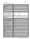
See “S.M.A.R.T. commands” on page 38.for details and subcommands used in the S.M.A.R.T. implementation.
Power
P1 V
33
3.3V power
P2 V
33
3.3V power
P3 V
33
3.3V power, pre-charge, 2nd mate
P4 Ground 1st mate
P5 Ground 2nd mate
P6 Ground 2nd mate
P7 V
5
5V power, pre-charge, 2nd mate
P8 V
5
5V power
P9 V
5
5V power
P10 Ground 2nd mate
P11 Ground or LED signal If grounded, drive does not use deferred spin
P12 Ground 1st mate.
P13 V
12
12V power, pre-charge, 2nd mate
P14 V
12
12V power
P15 V
12
12V power
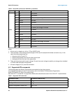
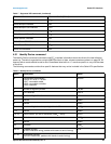
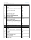
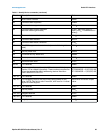
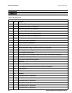
Table 7 Supported ATA commands
Command name Command code (in hex)
Check Power Mode E5
H
Configure Stream 51
H
Device Configuration Freeze Lock B1
H
/ C1
H
Table 6 Serial ATA connector pin definitions (continued)
Segment Pin Function Definition