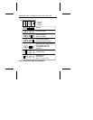
Master/slave timing protocol. This protocol involves the com-
munication between the computer and the disc drives during the
boot cycle only. The computer queries the master drive for the
status of both drives. The slave must report its status to the
master within a certain time period. If it does not respond, a
timeout error is issued and the computer does not identify the
slave. Place a jumper on pins 3 and 4 and on pins 5 and 6 to
extend the time period to 30 seconds that the Seagate master
waits for the slave to respond.
Cable-select. Use this configuration if your computer uses ca-
ble-select. Refer to your computer user’s manual.
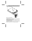
Remote LED. Place the ground wire side of the remote drive-ac-
tivity LED connector, usually the black wire, on pin 11 (–) and the
other side on pin 12 (+) of the options jumper block. The LED may
be damaged if the cable is attached incorrectly.
Attaching the cables
Required materials:
• A four-conductor power-supply cable
• A 40-conductor interface cable with a 40-pin, female interface
connector for each drive you want to attach.
Note. To ensure the integrity of your data, use a nonshielded
cable with a maximum length of 18 inches (46
centimeters).
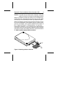
1. Attach the interface cable. Pin 1 on the drive must align with
pin 1 of the hard-disc controller connector. Use the edge-stripe
on the cable to denote pin 1. Pin 1 on the drive is located next
to the four-pin power connector.
8 Medalist SL Family Installation Guide, November 1995


