


24 Barracuda 18FC Installation Guide, Rev. A
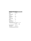
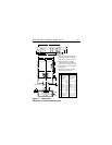
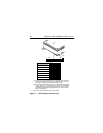
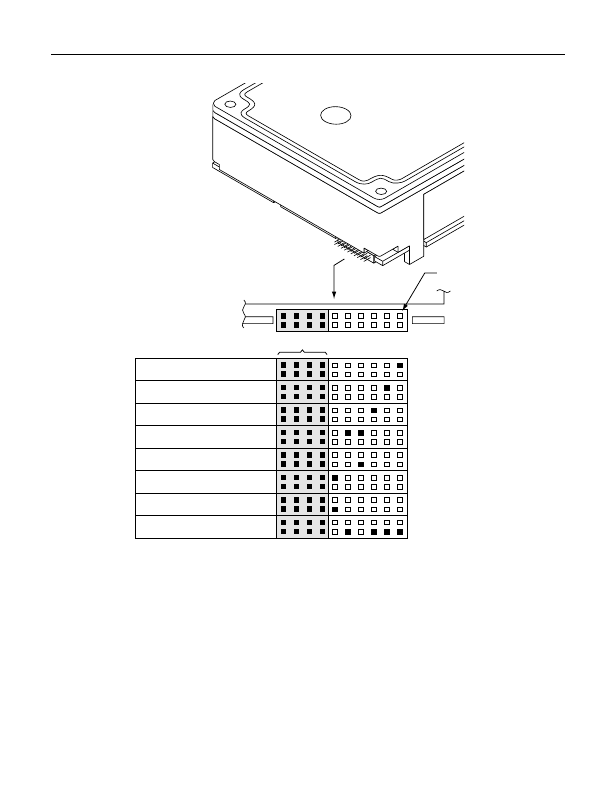
Figure 4: LED indicator connector (J6)
Drive
Front
Port A Bypass LED [1]
J6
Pin 1
Reserved
Port B Bypass LED [1]
Fault LED [1]
Reserved
Active LED [2]
+5V
Active LED [1]
Ground [3]
[1] The drive has a 2.2K ohm resistor in series with this LED driver.
Tie the minus side of an external high-efficiency LED (i.e., 2ma)
to this pin. Connect the plus side of the LED to +5V.
[2] An external current-limiting resistor is required when connecting
an LED to this pin. Connect the minus side of the resistor/LED
combination to this pin. Connect the plus side to +5V. This pin is
connected in parallel with the signal of the same name in the in-
terface connector (J1).
[3] Jumper storage location (across pins 2 and 4).