


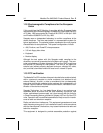
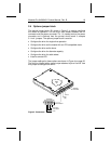

2.4 Options jumper block
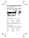
The options jumper block (J5), shown in Figure 3, is used to configure
the drives for operation. It is the 8-pin dual header between the I/O
connector and the power connector. Pin 1 is located next to the power
connector and is farthest from the printed circuit board. It accepts
0.1-inch jumpers. The options jumper block is used to:
• Configure the drive for single-drive operation.
• Configure the drive as the master with an ATA-compatible slave.
• Configure the drive as the slave.
• Configure the drive for alternate capacity.
• Configure the drive for cable select.
• Install a remote LED.
The jumper settings for these options are shown in Figure 4 on page 20.
The drive is shipped with a spare jumper attached to pins 6 and 8. Use
this jumper to configure the drive.
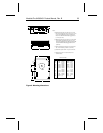
Circuit board
Standard
power connector
+5V
+5V return
+12V return
+12V
2
3
4
1
Interface
connector
Pin 1
Pin 1
(J5)
Figure 3. Connectors
Medalist Pro 6450/6451 Product Manual, Rev. B 19