


12 Lyrion CE-ATA Product Manual, Rev. A
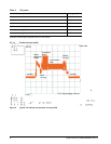
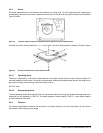
2.8.5 Shock
All shock measurements in this section are carried out at drive level. For all linear shock test, operating or
nonoperating, the input shock level is measured at the frame of the drive at the specific location as indicated in
Figure 3 below.
Figure 3. Location where tri-axial accelerometer will be placed on Lyrion Series drives
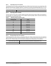
All shock test cover all the 6 directions, +/- x, y and z axes. The drive axis definition in shown in Figure 4 below.
Figure 4. Drive axis definition for Lyrion Series drives
2.8.5.1 Operating shock
The drive is subjected to 10 shocks for each direction. During the shocks, there must be a minimum delay of 3
seconds between shock pulses. Soft errors and automatic retries are allowed during the test. No data loss or
permanent damage occurs during a half sine shock pulse of:
500 G, 2 msec
2.8.5.2 Nonoperating shock
The nonoperating shock level that the drive can experience without incurring any physical damage when sub-
sequently put into operation is 1500 Gs. The same applies for shock levels of 1500 G, 1 msec pulse duration
on fresh drives for each level.
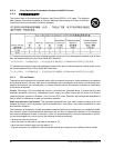
2.8.6 Vibration
All vibration specifications assume that the drive is mounted securely in a fixture that does not have fixture
resonances in the frequency test range.