


SEAGATE ENTERPRISE PERFORMANCE 15K HDD AND ENTERPRISE TURBO SSHD SAS PRODUCT MANUAL, REV. B 42
10.0 Installation
Enterprise Performance 15K HDD and Enterprise Turbo SSHD disk drive installation is a plug-and-play process. There are no jumpers,
switches, or terminators on the drive.
SAS drives are designed to be used in a host system that provides a SAS-compatible backplane with bays designed to accommodate the
drive. In such systems, the host system typically provides a carrier or tray into which the drive needs to be mounted. Mount the drive to the
carrier or tray provided by the host system using four M3 x 0.5 metric screws. When tightening the screws, use a maximum torque of 4.5
in-lb +/- 0.45 in-lb. Do not over-tighten or force the screws. Mount the drive in any orientation.
Note. SAS drives are designed to be attached to the host system without I/O or power cables. If it is intended to use the drive in a
non-backplane host system, connecting the drive using high-quality cables is acceptable as long as the I/O cable length does
not exceed 10 m (32.8 ft).
Slide the carrier or tray into the appropriate bay in the host system using the instructions provided by the host system. This connects the
drive
directly to the system’s SAS connector. The SAS connector is normally located on a SAS backpanel. See Section 11.4.1 for
additional information about these connectors.
Power is supplied through the SAS connector.
The drive is shipped from the factory low-level formatted in 512-byte logical blocks. Reformatting the driveis needed only if wanting to
select a different logical block size.
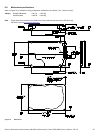
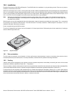
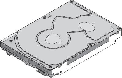
Figure 14. Physical interface
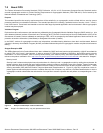
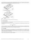
10.1 Drive orientation
The drive may be mounted in any orientation. All drive performance characterizations, however, have been done with the drive in
horizontal (disks level) and vertical (drive on its side) orientations, which are the two preferred mounting orientations.
10.2 Cooling
Cabinet cooling must be designed by the customer so that the ambient temperature immediately surrounding the drive will not exceed
temperature conditions specified in Section 6.5.1, "Temperature."
The rack, cabinet, or drawer environment for the drive must provide heat removal from the electronics and head and disk assembly (HDA).
Confirm that adequate heat removal is provided using the temperature measurement guidelines described in Section 6.5.1.
Forced air flow may be required to keep temperatures at or below the temperatures specified in Section 6.5.1 in which case the drive
should be oriented, or air flow directed, so that the least amount of air flow resistance is created while providing air flow t o the electronics
and HDA. Also, the shortest possible path between the air inlet and exit should be chosen to minimize the travel length of air heated by the
drive and other heat sources within the rack, cabinet, or drawer environment.