


Seagate Desktop SSHD Product Manual, Rev. C 15
www.seagate.com Configuring and Mounting the Drive
3.0 Configuring and Mounting the Drive
This section contains the specifications and instructions for configuring and mounting the drive.
3.1 Handling and static-discharge precautions
After unpacking, and before installation, the drive may be exposed to potential handling and electrostatic
discharge (ESD) hazards. Observe the following standard handling and static-discharge precautions:
Caution
• Before handling the drive, put on a grounded wrist strap, or ground oneself frequently by touching the metal
chassis of a computer that is plugged into a grounded outlet. Wear a grounded wrist strap throughout the entire
installation procedure.
• Handle the drive by its edges or frame only.
• The drive is extremely fragile—handle it with care. Do not press down on the drive top cover.
• Always rest the drive on a padded, antistatic surface until mounting it in the computer.
• Do not touch the connector pins or the printed circuit board.
• Do not remove the factory-installed labels from the drive or cover them with additional labels. Removal voids the
warranty. Some factory-installed labels contain information needed to service the drive. Other labels are used to
seal out dirt and contamination.
3.2 Configuring the drive
Each drive on the SATA interface connects point-to-point with the SATA host adapter. There is no master/slave
relationship because each drive is considered a master in a point-to-point relationship. If two drives are attached
on one SATA host adapter, the host operating system views the two devices as if they were both “masters” on two
separate ports. Both drives behave as if they are Device 0 (master) devices.
SATA drives are designed for easy installation. It is usually not necessary to set any jumpers on the drive for
proper operation; however, if users connect the drive and receive a “drive not detected” error, the SATA-equipped
motherboard or host adapter may use a chipset that does not support SATA speed autonegotiation.
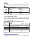
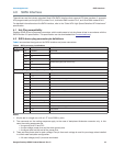
3.3 SATA cables and connectors
The SATA interface cable consists of four conductors in two differential pairs, plus three ground connections. The
cable size may be 30 to 26 AWG with a maximum length of one meter (39.37 inches). See Table 6 for connector
pin definitions. Either end of the SATA signal cable can be attached to the drive or host.
For direct backplane connection, the drive connectors are inserted directly into the host receptacle. The drive and
the host receptacle incorporate features that enable the direct connection to be hot pluggable and blind
mateable.
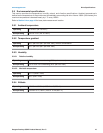
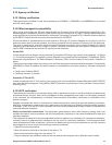
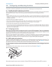
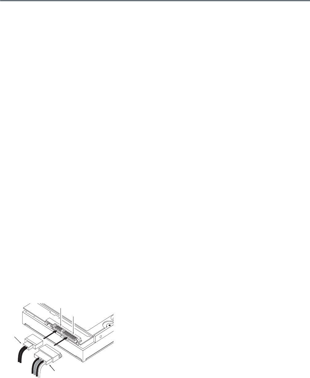
For installations which require cables, users can connect the drive as illustrated in Figure 2.
Figure 2 Attaching SATA cabling
Each cable is keyed to ensure correct orientation. Desktop SSHD drives support latching SATA connectors.
Power cable
Signal cable
Signal connector
Power connector