


24 SV35 Series SATA Product Manual, Rev. C
Configuring and Mounting the Drive www.seagate.com
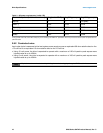
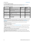
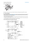
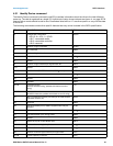
Figure 1 Attaching SATA cabling
Each cable is keyed to ensure correct orientation. Barracuda drives support latching SATA connectors.
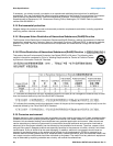
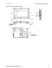
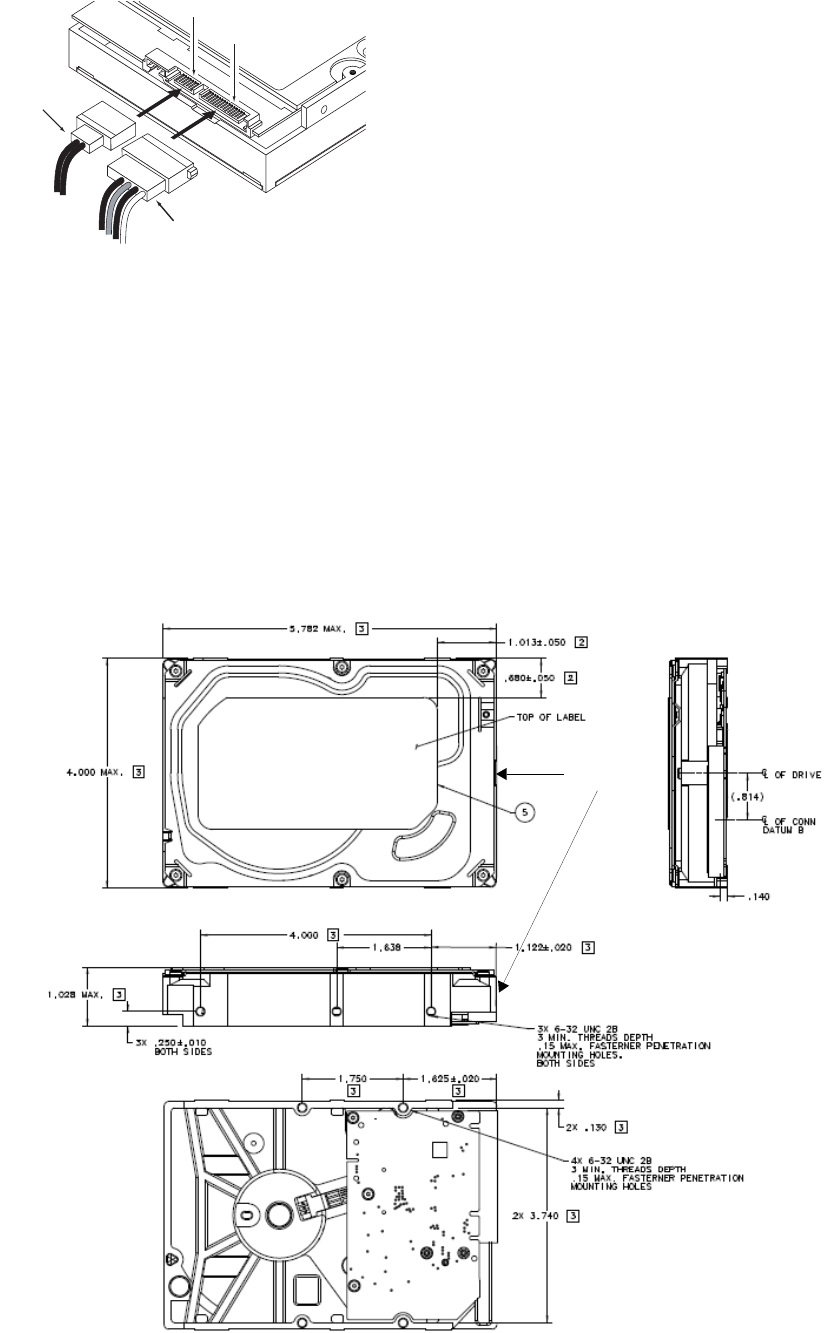
3.4 Drive mounting
You can mount the drive in any orientation using four screws in the side-mounting holes or four screws in the
bottom-mounting holes. See Figure 2 and Figure 3 for drive mounting dimensions. Follow these important
mounting precautions when mounting the drive:
• Allow a minimum clearance of 0.030 inches (0.76mm) around the entire perimeter of the drive for cooling.
• Use only 6-32 UNC mounting screws.
• The screws should be inserted no more than 0.150 inch (3.81mm) into the bottom or side mounting holes.
• Do not overtighten the mounting screws (maximum torque: 6 inch-lb).
Figure 2 Mounting dimensions (3-disk: 3TB and 2TB models)
Power cable
Signal cable
Signal connector
Power connector
Temperature
Check Point