


Hawk 4 (Wide) Family Install Guide, Rev. A 17
___________________________________________
Initial setup information
For the initial setup connect the cables, set the SCSI
bus address and enable or disable (as required by
system configuration), the SCSI I/O line terminator
resistors (model "W" drives only). Note whether the
drive model number ends in W, WC, DC or WD. These
procedures are described in paragraphs following.
SCSI interface cable connection
The drives covered by this manual are SCSI interface
drives. For "W" and "WD"" models, system connection
is via a 68 pin, SCSI connector. For "WC and DC"
models system connection is via an 80 pin SCSI
connector. Normally "WC and DC" models plug directly
into a PCB or bulkhead mounted mating 80 pin connec-
tor. Interfacing "WC and DC" models via a cable is not
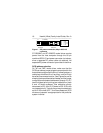
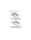
recommended. Pin 1 is noted in Figures 1a and 1b.
Some cables have a contrasting color stripe on one
edge to indicate pin 1. The I/O connector is keyed by
virtue of its shape. There is only one way it can mate
with the mating input connector. Strain relief is recom-
mended at the cable for drives using cables.
Do not
block system cooling air flow in routing of cables.
DC Power connection
Model ST15230W/WD family drives receive DC power
through a 4 pin connector mounted on the PCB next to
the SCSI I/O connector. See Figure 1.