


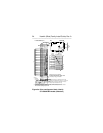
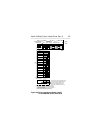
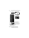
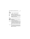
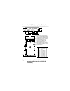
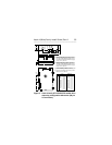
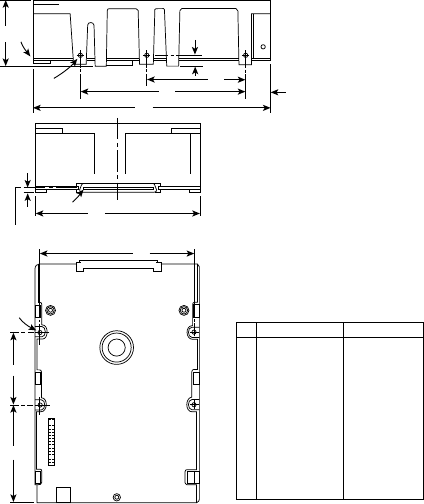
Figure 5. Hawk 4 family ST15230WC/DC model drive
mounting configuration dimension (80 pin
I/O connector)
A
F
D
E
C
[1]
[3]
B
G
J
H
K
[2]
Notes:
[1]
[2]
[3]
[4]
Inches Millimeters
5.74
4.00
1.620
2.362
.620
4.000
.250
1.750
3.750
2.370
0.181
145.80
101.60
41.15
60.00
15.75
101.60
6.35
44.45
95.25
60.20
4.597
A
B
C
D
E
F
G
H
J
K
L
0.010
0.010
0.026
0.021
0.010
0.010
0.010
0.018
0.010
0.010
0.010
0.018
0.013
±
±
+
–
±
±
±
±
±
±
±
+
–
.25
.25
.66
.53
.25
.25
.25
.46
.25
.25
.25
.45
.33
Mounting holes three on each side, 6-32 UNC.
Max screw length into side of drive 0.15 in.
(3.81 mm). Screw tightening torque 6.0 in-lb
(.675 NM) max with minimum thread engage-
ment of .12 in. (3.05 mm).
Mounting holes four on bottom, 6-32 UNC.
Max screw length into bottom of drive 0.20 in.
(5.08 mm). Screw tightening torque 6.0 in-lb
(.675 NM) max with minimum thread engage-
ment of .12 in. (3.05 mm).
Power and interface connections can extend past
the "A" dimension by 0.040 in. (1.02 mm).
Connector is centered (side to side) on drive
within ±0.020 in. (.508 mm).
±
±
+
–
±
±
±
±
±
±
±
+
–
L
Connector Centerline
[4]
Pin 1
Hawk 4 (Wide) Family Install Guide, Rev. A 35
___________________________________________