


Hawk 4 (Wide) Family Install Guide, Rev. A 27
___________________________________________
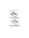
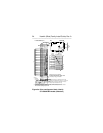
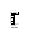
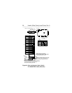
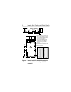
Notes for Figure 3a, 3b and 3c:
[1] Notes explaining the functions of the various jump-
ers on jumper header connectors J2, J1-auxiliary
and J6 are given below in left to right order of
jumper position. The term "default" means as
standard OEM units are configured when shipped
from factory. "Off" means no jumper is installed;
"On" means a jumper is installed. Off or On under-
lined is factory default condition.
[2] The PCB on "WC and DC" models does not have
connector J1-auxiliary, but has a single 80 pin
combined SCSI I/O and DC power connector in-
stead of the 68 pin SCSI I/O and 4 pin DC power
connectors. Included among the 80 pins are the
SCSI ID, Motor Start and Delayed Motor Start
select functions, and the remote LED signal. Do not
use J2 and J6 for these five functions if the host
uses the ones included in the 80 pin connector.
[3] Drive ID may be established by installing jumper
plugs in one of the patterns shown in Figures 3a, 3b
and 3c, or by plugging onto J6 or J1-auxiliary a
cable that leads to an external ID selection circuit.
Both jumper plugs and an external ID selection
source should not be used. See [4] for other func-
tions of these two headers that are time-shared
with the drive ID function.