Barracuda 9 Installation Guide, Rev. B 37
W/WD drives
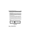
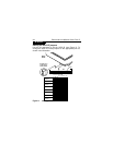
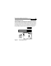
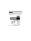
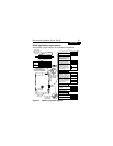
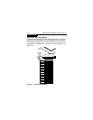
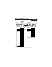
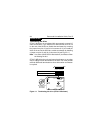
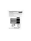
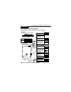
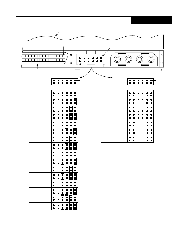
Figure 10. Using the J1 auxiliary jumper block
A
3
A
2
A
1
A
0
DC Power
Connector
68 Pin
SCSI I/O Connector
J1 Auxiliary
Pin 1
J1 Auxiliary
Drive HDA (rear view, PCB facing downward)
Pin 1
PCB
Pin 12
1P2P3P4P
Pins 2, 4, 6, and 8 are driven low
for 250 ms after PWR ON and reset
to allow jumper-selectable SCSI ID.
*
(default)
SCSI ID = 0
SCSI ID = 1
SCSI ID = 2
SCSI ID = 3
SCSI ID = 4
SCSI ID = 5
SCSI ID = 6
SCSI ID = 7
A
3
A
2
A
1
A
0
J1 Auxiliary
*Fault LED
*Vendor Unique
*Spindle Sync
*Activity LED
No Connection
Ground
+5V
SCSI ID = 8
SCSI ID = 9
SCSI ID = 10
SCSI ID = 11
SCSI ID = 12
SCSI ID = 13
SCSI ID = 14
SCSI ID = 15
Pin 1 Pin 1


