Barracuda 9FC Installation Guide, Rev. A 15
Mounting the drive
Do not touch the connector pins or any compo-
nents on the control board without observing static-
discharge precautions. Always handle the drive by
the frame only.
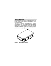
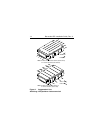
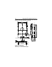
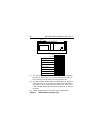
Mount the drive to the host system’s chassis using four 6-32
UNC screws. Two mounting holes are in each side of the drive
and there are four mounting holes in the bottom of the drive. See
Figure 3.
The maximum length that the screws should extend into the
chassis mounting holes is 0.15 inch (3.81 mm), measured from
the outer surface of the chassis. Tighten the screws down
evenly. Do not over-tighten or force the screw if it does not seem
to screw in easily.
Installation des Laufwerkes
Beachten Sie beim Handhaben und Anfassen der Anschlußstifte
und Komponenten die Vorsichtsmaßnahmen zur Verhinderung
statischer Aufladung. Fassen Sie das Laufwerk nur am Rahmen
an.
Befestigen Sie das Laufwerk mit vier 6-32-UNC-Schrauben am
Gehäuse des Host-Systems. Die beiden Seiten des Laufwerkes
sind mit jeweils zwei Befestigungslöcher versehen, die
Unterseite des Laufwerkes weist vier weitere Befestigungslöcher
auf. Siehe Abbiludung 3.
Gemessen von der Außenfläche des Gehäuses dürfen die
Schrauben maximal 3,81 mm in die Befestigungslöcher des
Gehüuses hineinragen. Die Schrauben müssen gleichmäßig,
jedoch nicht zu fest, angezogen werden. Wenn sich eine


