


24 Hawk 2LP (Wide) Installation Guide, Rev. A
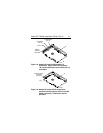
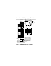
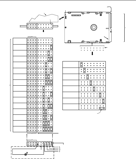
Drive with HDA up,
PCB down, viewed
from front
Pin 1
HDA
J6 [1]
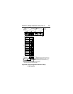
SCSI ID = 0
SCSI ID = 1
SCSI ID = 2
SCSI ID = 3
SCSI ID = 4
SCSI ID = 5
SCSI ID = 6
SCSI ID = 7
Reserved
J1-DC Power
Connector
J2
Drive Front
Pin 1
End
J6
SCSI I/O
Connector
J1-SCSI I/O
Pin 1
J2
A
2
A
1
J1-Auxiliary
A
0
See
Figure
3b
[3]
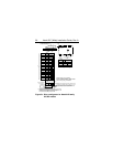
Delay
Motor Start
Enable
Motor Start
Write Protect
Parity Option
Term. Power
from Drive
Term. Power
to SCSI Bus
Term. Power
from SCSI Bus
Jumper
Positions
Position A
Enable
Terminator
T
E
D
S
M
E
W
P
P
E
S
S
T
P
T
P
[6]
[5]
[5]
[8]
[5]
SCSI ID = 8
SCSI ID = 9
SCSI ID = 10
SCSI ID = 11
SCSI ID = 12
SCSI ID = 13
SCSI ID = 14
SCSI ID = 15
Shipped with cover installed.
Do not install jumpers; retain cover
unless 20 pin plug is installed.
11 9 7 5 3 1
Remote LED
[4]
Optional connections to switching circuits
in host equipment to establish drive ID.
Pins 2, 4, 6 and 8 are driven low for
250 ms after PWR ON and reset to
allow jumper selectable SCSI ID.
Dashed area is optional host circuitry (external to the drive)
connected to host supplied optional usage plug. Drive PCB
circuitry for Pin 8 includes a 150 Ω series resistor.
Do not connect anything to pins 13-20.
+5V
Host
Alternate
Usage Plug:
Reserved
Pins
8 6 4 2
Ground
[4]
[4]
A
3
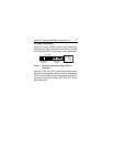
Figure 3a. Drive configurator Hawk 2LP family
W/WD model