


SEAGATE LAPTOP ULTRATHIN HDD SATA PRODUCT MANUAL, REV. C 16
SERIAL ATA (SATA) INTERFACE
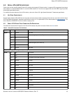
4.0 SERIAL ATA (SATA) INTERFACE
These drives use the industry-standard Serial ATA interface that supports FIS data transfers. It supports ATA programmed input/output
(PIO) modes 0–4; multiword DMA modes 0–2, and Ultra DMA modes 0–6. The drive also supports the use of the IORDY signal to provide
reliable high-speed data transfers.
For detailed information about the Serial ATA interface, refer to the Serial ATA: High Speed Serialized AT Attachment specification.
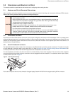
4.1 HOT-PLUG COMPATIBILITY
Seagate Laptop Ultrathin HDD SATA drives incorporate connectors which enable hot pluging of these drives in accordance with the Serial
ATA: High Speed Serialized AT Attachment specification revision 2.0. This specification can be downloaded from
www.serialata.org. This
device requires a COMRESET from the host after a hotplug event.
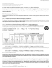
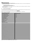
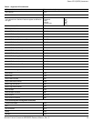
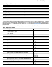
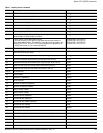
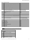
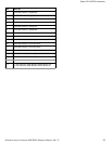
4.2 SERIAL ATA DEVICE PLUG CONNECTOR PIN DEFINITIONS
The table below summarizes the signals on the Serial ATA interface and power connectors. Refer to the Notes below.
Table 5 Serial ATA Connector Pin Definitions
Segment Pin Function Definition
Signal S1 Ground 2nd mate
S2 A+ Differential signal pair A from Phy
S3 A-
S4 Ground 2nd mate
S5 B- Differential signal pair B from Phy
S6 B+
S7 Ground 2nd mate
Key and spacing separate signal and power segments
Power P1 V
33
3.3V power
P2 V
33
3.3V power
P3 V
33
3.3V power, pre-charge, 2nd mate
P4 Ground 1st mate
P5 Ground 2nd mate
P6 Ground 2nd mate
P7 V
5
5V power, pre-charge, 2nd mate
P8 V
5
5V power
P9 V
5
5V power
P10 Ground 2nd mate
P11 Ground or LED signal If grounded, drive does not use deferred spin
P12 Ground 1st mate
P13 V
12
12V power, pre-charge, 2nd mate
P14 V
12
12V power
P15 V
12
12V power