


Seagate Kinetic HDD Product Manual, Rev. A 20
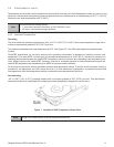
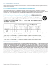
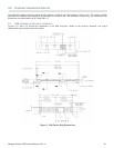
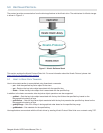
Figure 4.1.3 shows the pin locations for the SAS connector pin and Table 4.1.1 represents the Ethernet Enabled SAS
Connector Pin Definitions for the Seagate Kinetic HDD.
Figure 5 SAS Connector Pin Locations
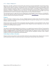
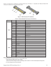
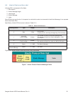
Table 12: Ethernet Enabled SAS Connector Pin Definitions
Notes
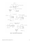
• All pins are in a single row, with a 1.27 mm (0.050”) pitch.
• There are three power pins for each voltage.
One pin from each voltage is used for pre-charge when installed in a blind-mate backplane configuration.
•All used voltage pins must be terminated.
Segment Pin Function Comments
Signal
S1 GROUND
S2 RX0+ Ethernet port 0
S3 RX0- Ethernet port 0
S4 GROUND
S5 TX0- Ethernet port 0
S6 TX0+ Ethernet port 0
S7 GROUND
S8 GROUND
S9 RX1+ Ethernet port 1
S10 RX1- Ethernet port 1
S11 GROUND
S12 TX1- Ethernet port 1
S13 TX1+ Ethernet port 1
S14 GROUND
Power
P1 RESERVED Reserved for internal use. Do not connect. 3.3V tolerant.
P2 I2C CLOCK 3.3V tolerant
P3 I2C DATA 3.3V tolerant
P4 GROUND
P5 GROUND
P6 GROUND
P7 +5V PRECHARGE
P8 +5V
P9 +5V
P10 GROUND
P11 RESERVED Reserved for internal use. Do not connect.
P12 GROUND
P13 +12V PRECHARGE
P14 +12V
P15 +12V